
Electromechanical valve

A valve, electromechanical technology, applied in the direction of lift valve, circuit, electromagnet, etc., can solve the problems of dust sensitivity, easy wear, easy to block the working medium and so on

Active Publication Date: 2016-10-12
STACCATO TECH
View PDF5 Cites 3 Cited by
  • Summary
  • Abstract
  • Description
  • Claims
  • Application Information

AI Technical Summary

Problems solved by technology

[0002] The disadvantages of existing electromechanical valves are low efficiency, long response time, sensitivity to dust, easy wear, easy jamming, and easy leakage of working medium, etc.

Method used


Image

  • Electromechanical valve
  • Electromechanical valve
  • Electromechanical valve

Examples


Embodiment Construction

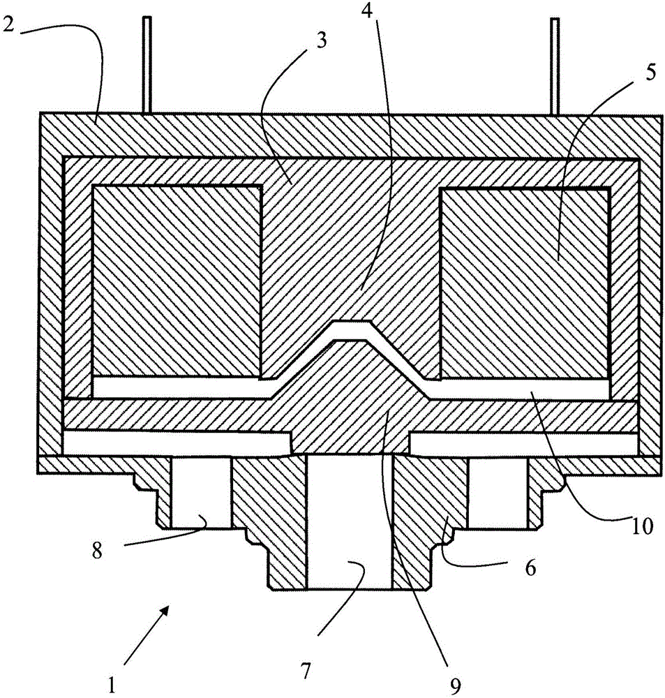
[0023] figure 1 An axial sectional view of an embodiment of an electromechanical valve 1 , for example a pneumatic valve, is shown. The valve can be designed to operate with fluids other than air.

[0024] The electromechanical valve 1 comprises a housing 2 made of a non-magnetic material such as aluminium. Inside the housing 2 is a core 3 made of electromagnetic material. The core 3 has a central extension 4 around which a coil 5 surrounds. In one embodiment, the core 3 is generally cup-shaped. In one embodiment, the core 3 may be U-shaped. Other shapes are also possible, eg E-shape.

[0025] In one embodiment, the central portion 4 extends to the edge of the cup-shaped magnetic core 3 . It should be understood, however, that the portion 4 may be shorter or longer than the height of the wall of the core.

[0026] The coil 5 is supplied via its terminals with excitation current from a current source, as hereinafter incorporated Figure 13 shown.

[0027] Preferably, t...


PUM

PropertyMeasurementUnit
Thicknessaaaaaaaaaa

Abstract

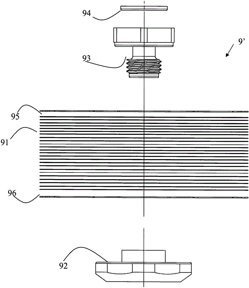
An electromechanical valve comprises a housing, a core (3') of magnetic material surrounded by a coil to be supplied with excitation current, a valve seat attached to the housing with a space to said core (3'), at least one outlet port in said valve seat and at least one inlet port communicating via said space, and a valve washer (9') of magnetic material arranged in said space. The valve washer is formed by multiple stacked plates (91, 95, 96) that are at least partially displaceable in relation to each other.

Description

technical field [0001] The present invention generally relates to the field of valves, in particular to an electromechanical valve. Background technique [0002] The disadvantages of existing electromechanical valves are low efficiency, long response time, sensitivity to dust, easy wear, easy jamming, and easy leakage of working medium. An electromechanical valve of the type described in WO2008 / 156405 can improve the performance of an electromechanical valve. [0003] There is an ongoing quest to improve the performance and robustness of electromechanical valves. Therefore, it is necessary to improve the electromechanical valve. Contents of the invention [0004] It is an object of the present invention to overcome or at least partially alleviate the disadvantages of existing electromechanical valves and to provide an improved electromechanical valve. [0005] These and other objects are achieved at least in part by the electromechanical valve of the present invention a...

Claims


Application Information

Patent Timeline
IPC IPC(8): F16K31/06
CPCF16K1/36F16K31/0655F16K31/0658H01F7/081H01F7/14H01F7/1638H01F2007/086
Inventor P-O·约翰松
Owner STACCATO TECH
Learn More