Inductively coupled power transfer (ICPT) device with pull-down auxiliary switch

An auxiliary switch and power transmission technology, applied in the field of electricity, can solve the problems of unfavorable application and promotion of new ICPT device topology, reduction of ICPT device volume and cost, and burnout of the switch tube, which is beneficial to application promotion and volume reduction , the effect of short turn-on time

Active Publication Date: 2017-09-05
QINGDAO UNIV
View PDF5 Cites 9 Cited by
  • Summary
  • Abstract
  • Description
  • Claims
  • Application Information

AI Technical Summary

Problems solved by technology

[0003] At present, the main circuit topology of Inductively Coupled Power Transfer (ICPT) devices mostly adopts full-bridge voltage type inverter circuit, half-bridge LLC voltage type resonant inverter circuit and LC resonant single tube inverter bipolar inverter circuit; the first two circuit topologies have relatively complex circuit structures, relatively high power supply costs, and the upper and lower switch tubes of the bridge arm are likely to cause straight-through and burn out; the latter is a new type of wireless power transmission topology with simple circuits and low cost. low, high transmission efficiency, zero voltage turn-on and zero voltage turn-off control can be realized, but there are also some disadvantages, when the input voltage of the device is 220V ac / 50Hz alternating current, the voltage at both ends of the switch tube is as high as 1200V or more during its operation, so that the switch tube can only use an insulated gate field effect transistor (IGBT) with a higher withstand voltage. In order to reduce the volume and weight of the ICPT device, The national standard stipulates that the switching frequency must be above 83kHz, and when the switching frequency of the IGBT is greater than 25kHz, its loss will increase with the increase of the switching frequency, which restricts the further reduction of the size and cost of the ICPT device, which is not conducive to this new type of ICPT. Application promotion of device topology

Method used


Image

  • Inductively coupled power transfer (ICPT) device with pull-down auxiliary switch
  • Inductively coupled power transfer (ICPT) device with pull-down auxiliary switch
  • Inductively coupled power transfer (ICPT) device with pull-down auxiliary switch

Examples


Embodiment

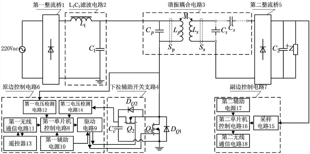
[0019] The main structure of the ICPT device with the pull-down auxiliary switch involved in this embodiment includes the first rectifier bridge 1, L 1 C 1 Filter circuit 2, resonant coupling circuit 3, main switching tube Q 1 , the first diode D Q1 , pull-down auxiliary switch branch 4, second rectifier bridge 5, second filter capacitor C 2 , equivalent load Z, primary side control circuit 6 and secondary side control circuit 7; 220V ac Through the first rectifier bridge 1, L 1 C 1 After filtering circuit 2, it is converted into a DC voltage, and the main switching tube Q 1 , the first diode D Q1 and pull-down auxiliary switch branch 4 to invert the direct current into high-frequency alternating current, and the high-frequency alternating current is applied to the primary side inductance L in the resonant coupling circuit 3 p The two ends of the resonant coupling circuit 3 secondary inductance L s The voltage is induced at both ends, and the secondary inductance L s ...


PUM


Abstract

The invention belongs to the field of electronic technology, and relates to an inductively coupled power transfer (ICPT) device with a pull-down auxiliary switch. A group of pull-down auxiliary switch branch is added to an LC resonant single tube inverting bipolar inverting circuit topology used by the existing ICPT device, the branch comprises an auxiliary switch tube, a main switch tube and the auxiliary switch tube have the same switch frequency, soft switch control can be both realized, no shoot-through problem exists between the two tubes, and the reliability is improved. In a condition of keeping the advantages of the original circuit, voltage borne at two ends of the switch tube is reduced to 2/3 the original voltage, the device can adopt a metal oxide transistor as a switch tube, the switch frequency can reach more than 83kHz, and as the auxiliary switch tube is short in turn-on time and low in power consumption, a technical scheme for furthering reducing the size and the weight of the ICPT device and reducing the cost is provided.

Description

[0001] Technical field: [0002] The invention belongs to the field of electrical technology, and relates to an inductively coupled electric energy transmission device with a pull-down auxiliary switch. The auxiliary switch branch is used for the occasion of inductively coupled electric energy transmission. Background technique [0003] At present, the main circuit topology of Inductively Coupled Power Transfer (ICPT) devices mostly adopts full-bridge voltage type inverter circuit, half-bridge LLC voltage type resonant inverter circuit and LC resonant single tube inverter bipolar inverter circuit; the first two circuit topologies have relatively complex circuit structures, relatively high power supply costs, and the upper and lower switch tubes of the bridge arm are likely to cause straight-through and burn out; the latter is a new type of wireless power transmission topology with simple circuits and low cost. low, high transmission efficiency, zero voltage turn-on and zero vo...

Claims


Application Information

Patent Timeline
Patent Type & Authority Applications(China)
IPC IPC(8): H02M3/335H02J50/12G08C17/02
CPCG08C17/02H02J5/005H02J7/025H02M3/33523Y02B70/10
Inventor 王春芳魏芝浩李震
Owner QINGDAO UNIV
Why Eureka
Try Eureka