Support structure for a wing

a support structure and wing technology, applied in the field of statics, can solve the problems of increasing the weight of the highly loadable framework, the inability of sarma® rods to meet the requirements of high load, and the need for relatively solid bars. to achieve the effect of improving the support structur

Active Publication Date: 2010-07-08
AIRBUS OPERATIONS GMBH
View PDF8 Cites 16 Cited by
  • Summary
  • Abstract
  • Description
  • Claims
  • Application Information

AI Technical Summary

Benefits of technology

[0009]It may be an object to provide an improved support structure for an aircraft.

Problems solved by technology

While such profiles are suitable for constructing highly loadable frameworks, these bars will then however have to be relatively solid.
This results in an increase in the weight of the highly loadable framework.
However, due to their insufficient dimensioning, SARMA® rods are not suitable for highly loaded frameworks.
In particular, at the so-called framework junction points, i.e., at the end of the framework bars, complex and heavy connections must be used.
On the one hand, this results in disadvantages in the case of production errors because the large components have to be repaired at considerable expenditure.
On the other hand, in particular by using ribs, it is not possible to transfer introduced loads, such as for example, loads that result from pressure forces or tensile forces during flight manoeuvres of an aircraft, in the shortest way to the fuselage connection.

Method used


Image

  • Support structure for a wing
  • Support structure for a wing
  • Support structure for a wing

Examples


Embodiment Construction

[0097]The examples described and drawings rendered are illustrative and are not to be read as limiting the scope of the invention as it is defined by the appended claims. The features shown in the drawings are not on scale. Same or similar features in different drawings are labelled with the same or similar reference signs.

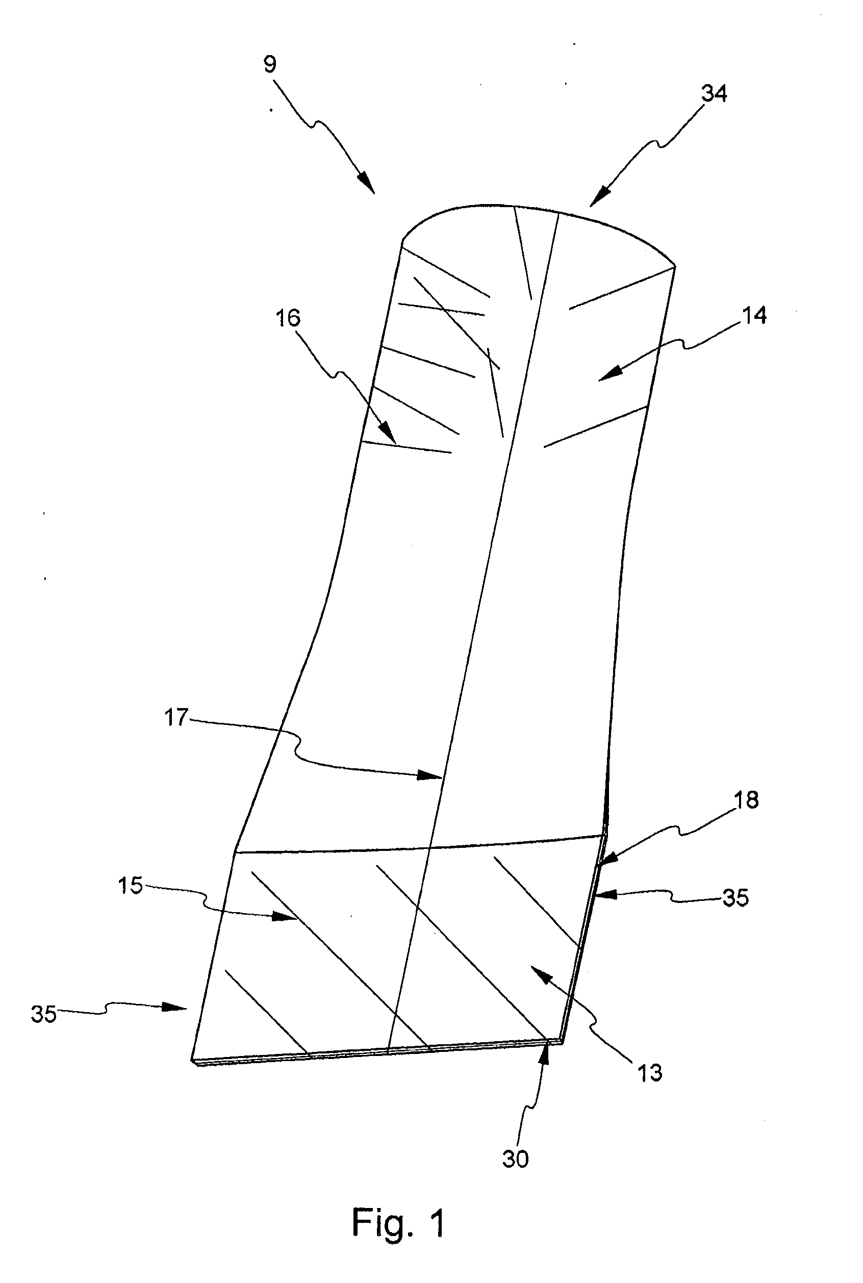
[0098]FIG. 1 shows a top view of a connection element 9. The connection element 9 forms the transition from a round cross section 34 to a narrow rectangular cross section 30. On its round end 34 or on its round cross section 34, which may receive a tube, the connection element 9 comprises an aperture for accommodating a tube. In the non-fastened state, an inserted tube or bar element may be slid along the accommodation region or attachment region 14. As an alternative, the accommodation region 14 may also be inserted into a tube. In the non-fastened state, a tube inserted into the attachment region 14 may be slid along the center line 17 or may be rotated on the c...


PUM


Abstract

A support structure for an aircraft, includes one or several bar elements and one or several junction elements. At least one bar element includes a transition region which can be made to engage at least one junction element. When the transition region of the bar element engages at least one junction element, centric force transmission takes place between the bar element and the junction element.

Description

REFERENCE TO RELATED APPLICATIONS[0001]This application claims the benefit of the filing date of U.S. Provisional Patent Application No. 60 / 709,146 filed Aug. 17, 2005 and of German Patent Application No. 10 2005 038 849.3 filed Aug. 17, 2005, the disclosures of each of which is hereby incorporated herein by reference.FIELD OF THE INVENTION[0002]The field generally relates to the technical field of statics. In particular, the field relates to a support structure, a connection element, a junction element for a support structure, a wing, a method for force transmission between a bar element and a junction element, a method for producing a connection element, the use of a support structure in an aircraft, and an aircraft comprising a support structure.BACKGROUND[0003]In the construction of aircraft, highly loaded frameworks comprising U-profiles or double T-profiles are built. Furthermore, bars with rectangular profiles are frequently used, for example, in the lower ribs of the center ...

Claims


Application Information

Patent Timeline
Patent Type & Authority Applications(United States)
IPC IPC(8): B64C3/00B64C1/06F16B7/00
CPCB64C1/26B64C3/00Y10T403/4381B64C5/06E04B2001/193B64C3/26
Inventor MAENZ, CHRISTIAN
Owner AIRBUS OPERATIONS GMBH
Why Eureka
Try Eureka