
Bundling of driver assistance systems

a driver assistance and system technology, applied in the field of driver assistance systems, can solve the problems of color filters with imaging sensors that may preclude the simultaneous use of the same image frame for other driver assistance applications, preclude the use of the same sensor, and electronic signs are not uniform across all countries

Active Publication Date: 2010-07-08
MOBILEYE VISION TECH LTD
View PDF11 Cites 137 Cited by
  • Summary
  • Abstract
  • Description
  • Claims
  • Application Information

AI Technical Summary

Benefits of technology

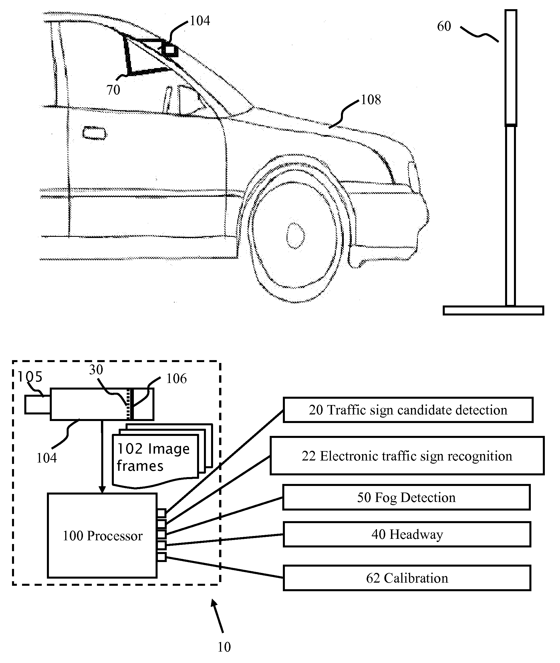
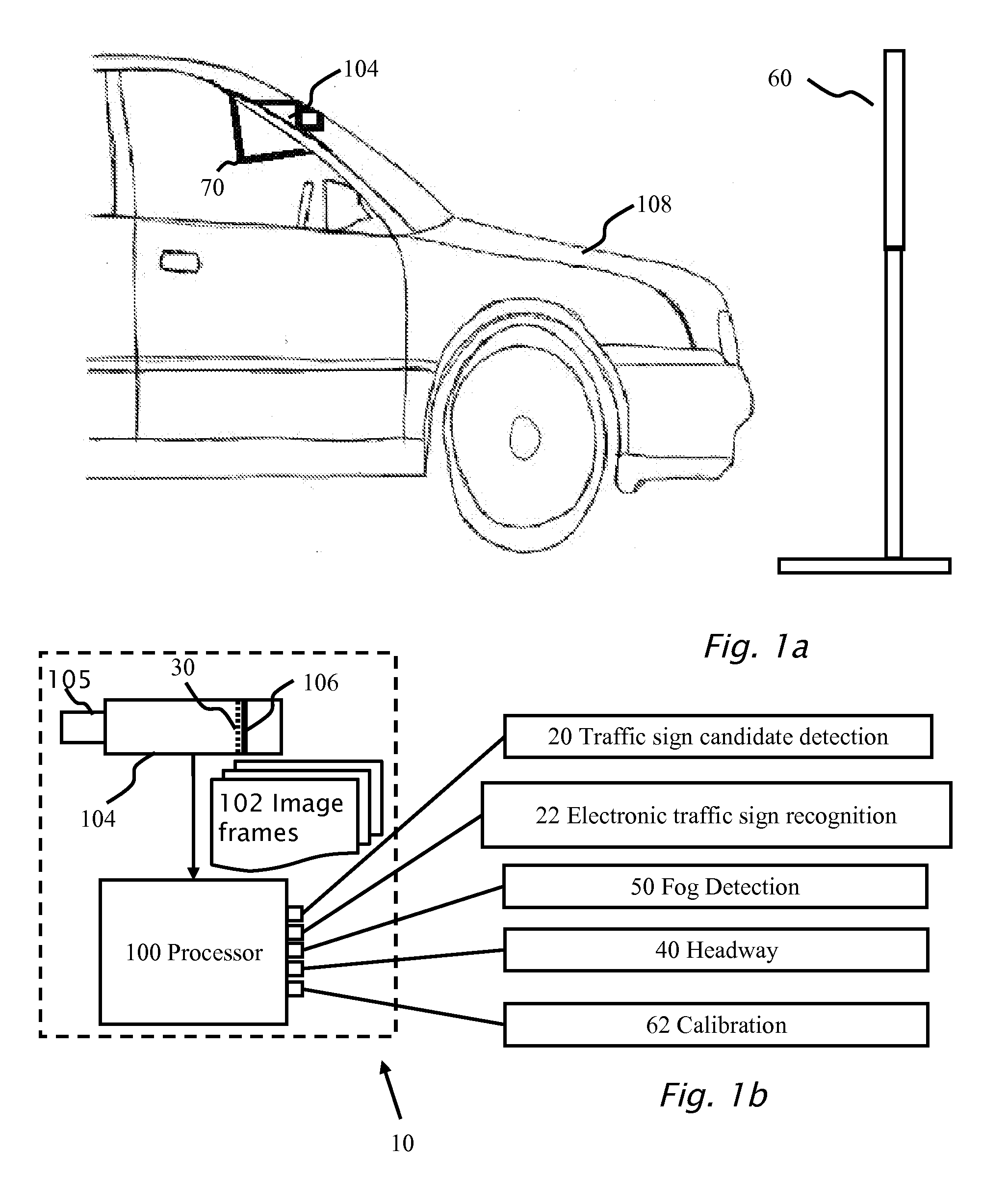
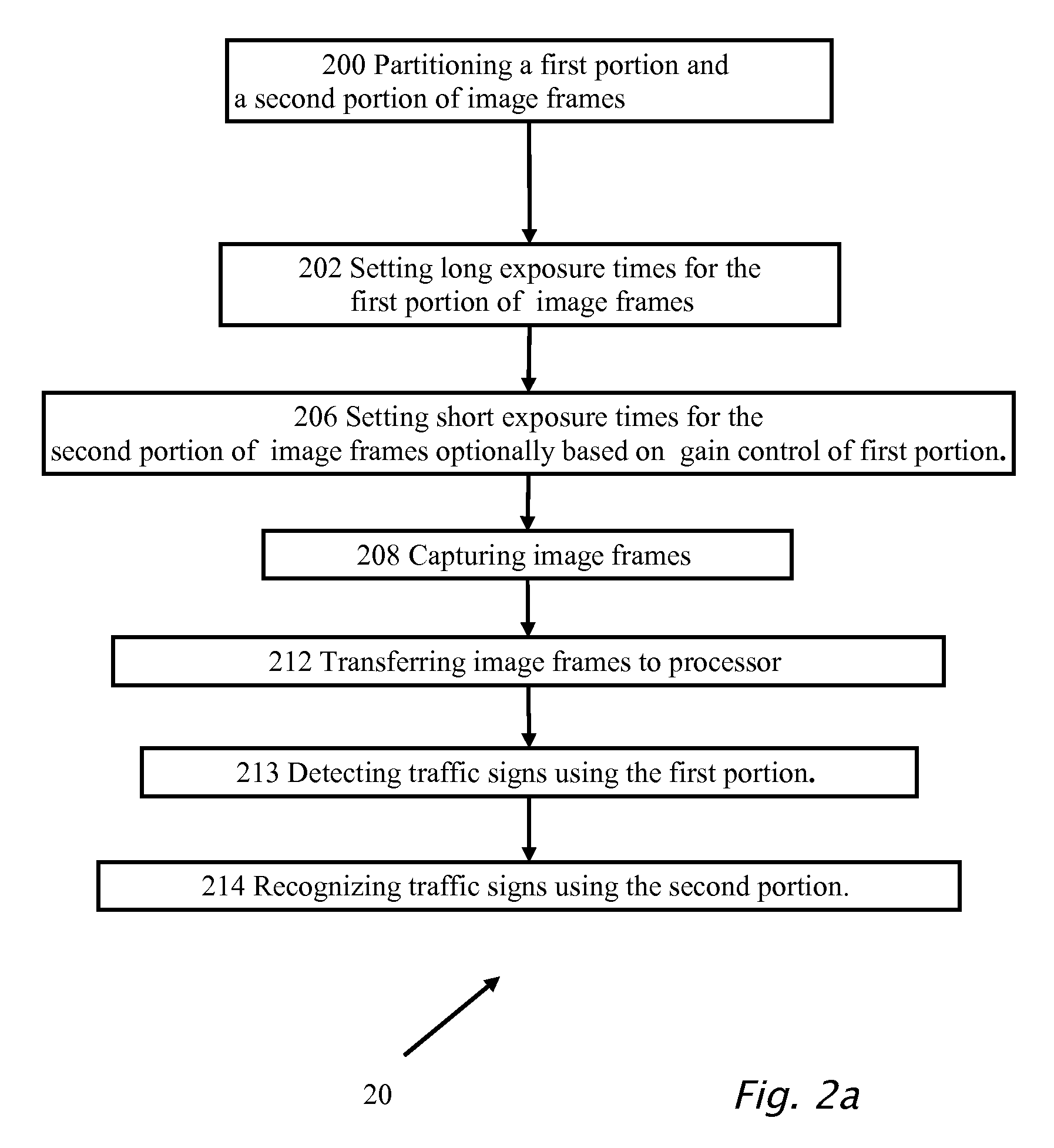
[0023]According to an embodiment of the present invention there is provided a method for performing a driver assistance function using a computerized system mounted on a moving vehicle. The computerized system includes a camera and an image processor. Under control of the image processor the camera is adapted for capturing in real time image frames of the environment in the field of view of the camera. A first portion and a second portion of the image frames are partitioned. For the first portion, a camera parameter is controlled based on ambient lighting conditions in the environment in the field of view of the camera. Based on the camera parameter of the first portion, a camera parameter of the second portion is set. The image frames are captured and transferred to the image processor for processing of the driver assistance function. The camera parameters of the first and second portions are gain and / or exposure time. When the driver assistance function includes detection and recognition of traffic signs, the detection of the traffic signs uses the first portion of the image frames and the recognition of the traffic sign uses the second portion of the image frames. When the traffic sign is an electronic traffic sign, both the first portion of the image frames and the second portion of the image frames may be used for recognition of the traffic sign. The electronic traffic sign may be a pulsed electronic traffic sign, a variable message traffic sign and / or a back-lit traffic sign. For the second portion of the image frames, a short exposure time is set which is substantially shorter than the exposure time of the first portion. The camera parameter of the second portion of the image frames is set substantially differently between day-mode operation during the day and night-mode operation during the night. Optionally the camera parameter of the second portion is set substantially differently during dusk for dusk-mode operation than during the day-mode operation and / or the camera parameter of the second portion is set substantially differently during dusk for dusk-mode operation than during the night-mode operation.

Problems solved by technology

Expectation with 99% availability is particularly challenging to achieve in low light conditions when the lane markings are not freshly painted (have low contrast with the road) and the only light source is the car halogen headlights.
The use of color filters with imaging sensors may preclude the simultaneous use of the same image frames for other driver assistance applications.
The color mosaic filter may preclude the use of the same sensor for traffic sign recognition (TSR) or lane departure warning (LDW) because of the intensity response penalty.
Moreover, electronic signs are not uniform across all countries and even vary according to the time of day and ambient light levels.

Method used


Image

  • Bundling of driver assistance systems
  • Bundling of driver assistance systems
  • Bundling of driver assistance systems

Examples


embodiment 1

Axis of Rotation Close to the Glass

[0183]A camera mount 70 is desirable that allows adjustment of the camera angle but enforces a constraint that camera lens 105 touches glass 701. Reference is now made to FIGS. 7b and 7c which show an embodiment of camera mount 70 according to the present invention. In FIG. 7b, camera 104 is shown butted up against windshield glass 701 shown at two different angles. Camera mount 70 includes a fixed element 707 mounted flush with windshield 701. Reference is now also made to FIG. 7c which illustrates the embodiment of camera mount 70 of FIG. 7b in more detail. An axis 703 of rotation has been shifted to the tip of lens 105 where the lens mount 105 touches the glass. The body of camera 104 has two extensions 705 one on each side of lens 105. The tip of extension 705 is in line with upper edge of lens 105. From each extension 705, axis pin 703 is attached which is parallel to the glass plane. Axis pins 703 fit into corresponding holes in extension 705...

embodiment 2

Semicircle Design

[0186]Reference is now made to FIG. 7e which illustrates two views of a second embodiment of the present invention. The two views differ by the angles of windshield 701. As camera 104 is rotated so that the tip of lens 105 touches glass 701 at point 703, the opposite corner 704 of camera body 104 marks a circular path whose center is point 703 of contact between lens 105 and glass 701. Since opposite corner 704 is the most distant point on camera 104 from the tip of lens 105, the semi-circle shown encloses all of camera 104 during adjustment. Reference is now also made to FIGS. 7f and 7g which show a side view and rear view respectively, of camera mount 70, according to an embodiment of the present invention. Camera body 104 may be modified so that instead of a sharp corner at point 704 it has a flat or beveled surface 704 at the point of contact with a semi-circular strip 714. It should be noted that the flat surface at point 704 is perpendicular to a radius of sem...


PUM


Abstract

A traffic sign recognition system including a detection mechanism adapted for detecting a candidate traffic sign and a recognition mechanism adapted for recognizing the candidate traffic sign as being an electronic traffic sign. A partitioning mechanism may be adapted for partitioning the image frames into a first partition and a second partition. The detection mechanism may use the first portion of the image frames and the recognition mechanism may use the second portion of the image frames. When the candidate traffic sign is detected as an electronic traffic sign, the recognition mechanism may use both the first partition of the image frames and the second portion of the image frames.

Description

CROSS REFERENCE TO RELATED APPLICATIONS[0001]This application is a continuation-in-part of pending application Ser. No. 11 / 951,405, filed Dec. 6, 2007.[0002]The present application claims the benefits of U.S. provisional applications Nos. 61 / 102,893 filed Oct. 6, 2008; 61 / 193,527 filed Dec. 5, 2008; 61 / 193,528 filed Dec. 5, 2008; 61 / 141,003 filed Dec. 29, 2008; 61 / 141,005 filed Dec. 29, 2008; 61 / 150,034 filed Feb. 5, 2009; and 61 / 165,190, filed Apr. 9, 2009, the disclosures of which are incorporated by reference in their entireties.BACKGROUND[0003]1. Technical Field[0004]The present invention relates to multiple driver assistance systems and more specifically to the integration of the driver assistance systems onto a single hardware platform.[0005]2. Description of Related Art[0006]During the last few years camera based driver assistance systems (DAS) have been entering the market; including lane departure warning (LDW), Automatic High-beam Control (AHC), traffic sign recognition (T...

Claims


Application Information

Patent Timeline
Patent Type & Authority Applications(United States)
IPC IPC(8): G06K9/00H04N7/18B60Q1/26G06V10/147
CPCG06K9/00798G06K9/00818G06K9/209G06T7/0018G08G1/0967G06T2207/20164G06T2207/30204G06T2207/30252G06T2207/10004G06T7/80G06V20/582G06V20/588G06V10/147G03B43/00G03B37/04G06T7/12G06T2207/10144
Inventor STEIN, GIDEONSHACHAR, ORIBELMAN, EFIMHAYON, GABYGAT, ITAY
Owner MOBILEYE VISION TECH LTD
Learn More