Hydraulically and electrically actuated articulation joints for surgical instruments

a technology of articulation joints and surgical instruments, applied in the field of surgical instruments, can solve the problems of exacerbated problems, high torque generation of firing structure, complicated approaches to articulating surgical stapling and severing instruments,

Active Publication Date: 2010-07-15
CILAG GMBH INT
View PDF109 Cites 263 Cited by
  • Summary
  • Abstract
  • Description
  • Claims
  • Application Information

AI Technical Summary

Benefits of technology

[0075]The various non-limiting embodiments of the present invention provide a host of advantages over prior art articulated surgical instruments. In particular, the various embodiments of the subject invention enable the portions of the tube member that attach a surgical implement to a handle to be inserted through a trocar or similar device and then be selectively articulated within the patient. While the various embodiments have been described herein in connection with use with a hydraulically operated endocutter, those of ordinary skill in the art would appreciate that the various embodiments of the subject invention could be employed with electrically powered endocutters and with a host of other types of surgical implements, regardless of whether they are electrically or hydraulically powered.

Problems solved by technology

Approaches to articulating a surgical stapling and severing instrument tend to be complicated by integrating control of the articulation along with the control of closing the end effector to clamp tissue and fire the end effector (i.e., stapling and severing) within the small diameter constraints of an endoscopic instrument.
Due to the types end effector firing systems commonly employed, the actuator arrangements for articulating the end effector must often generate high amounts of torque to bend the firing structure.
This problem is exacerbated by the lack of available space for accommodating actuating devices that are large enough to generate those required forces.

Method used


Image

  • Hydraulically and electrically actuated articulation joints for surgical instruments
  • Hydraulically and electrically actuated articulation joints for surgical instruments
  • Hydraulically and electrically actuated articulation joints for surgical instruments

Examples


Embodiment Construction

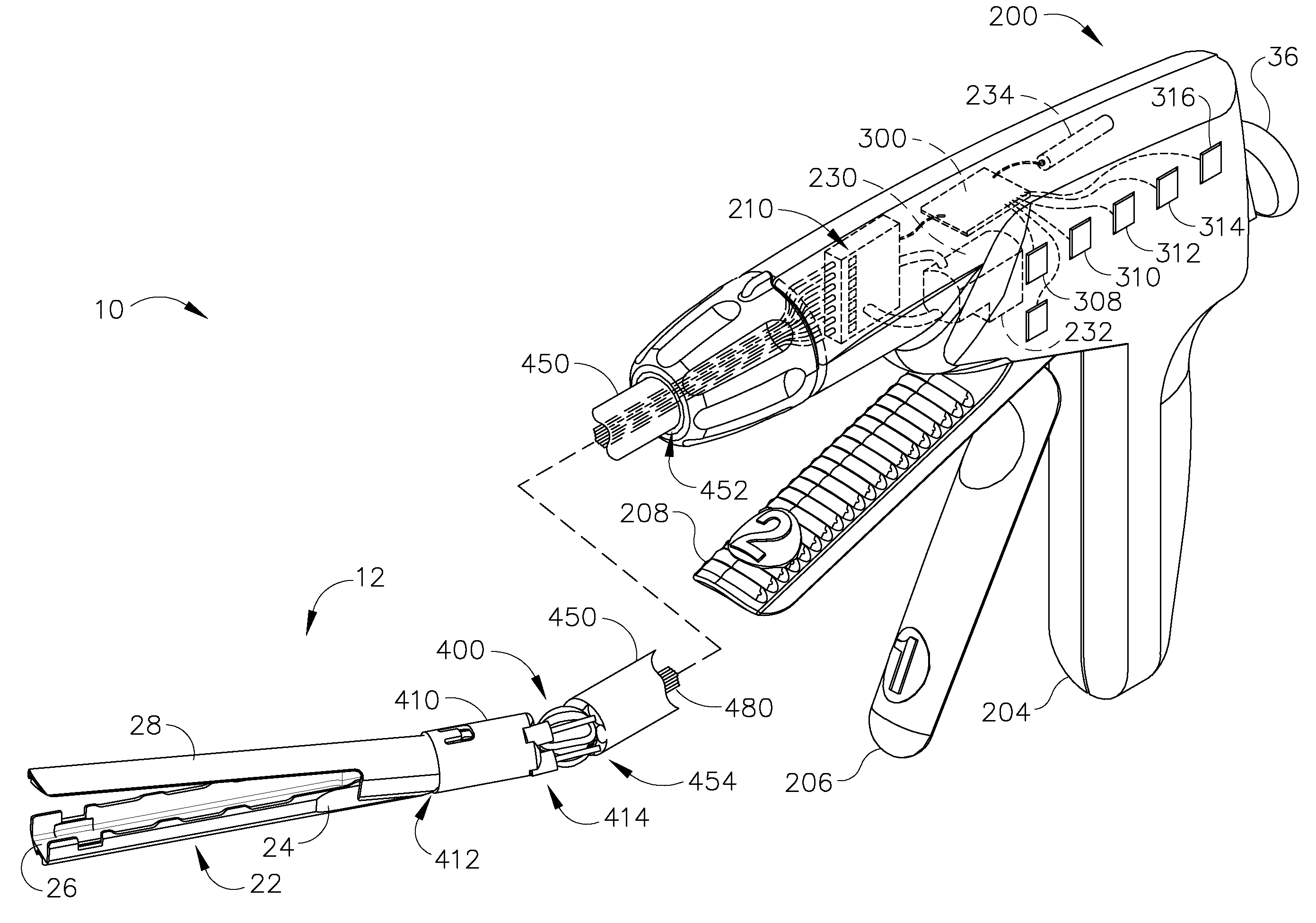
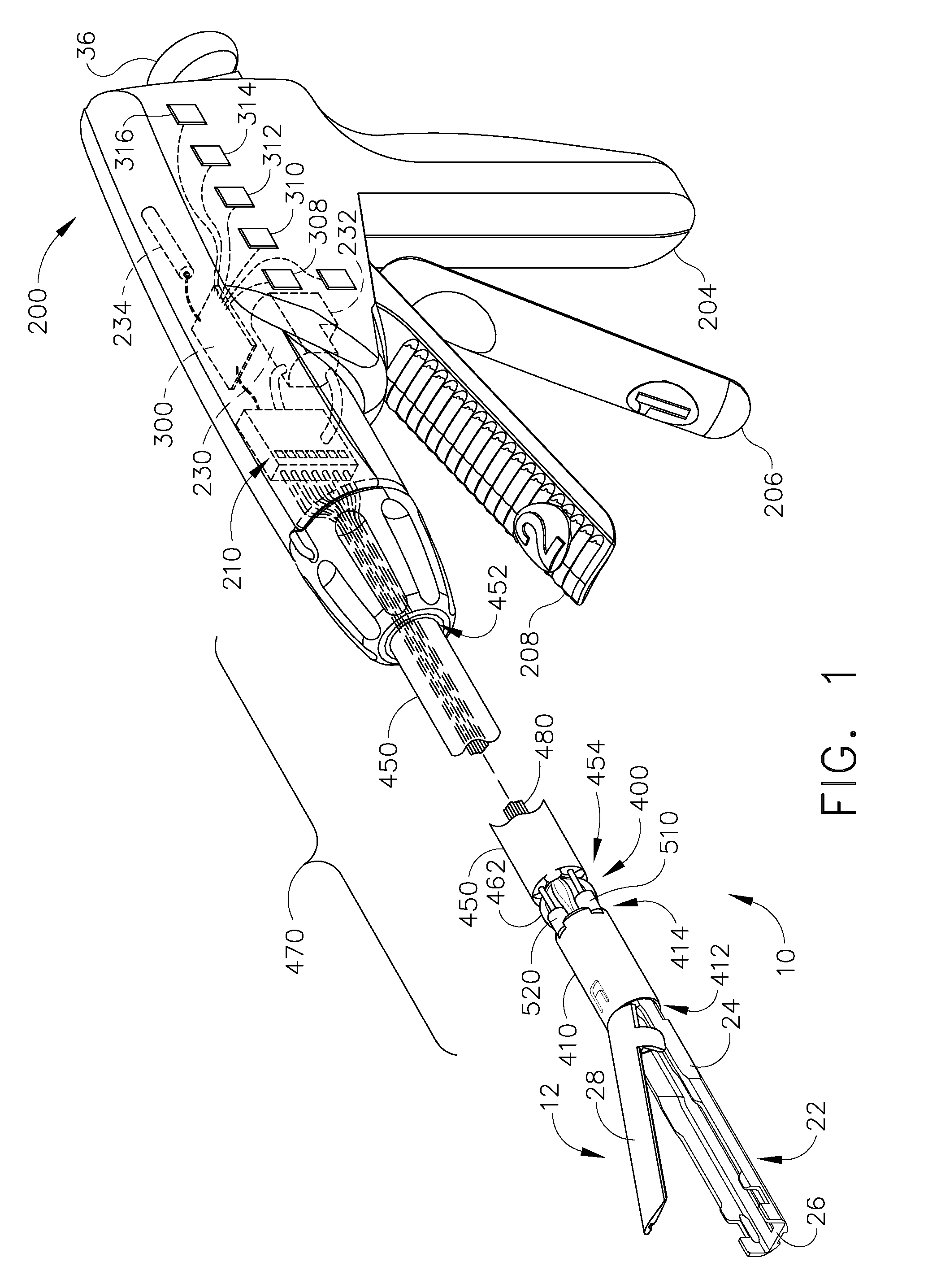
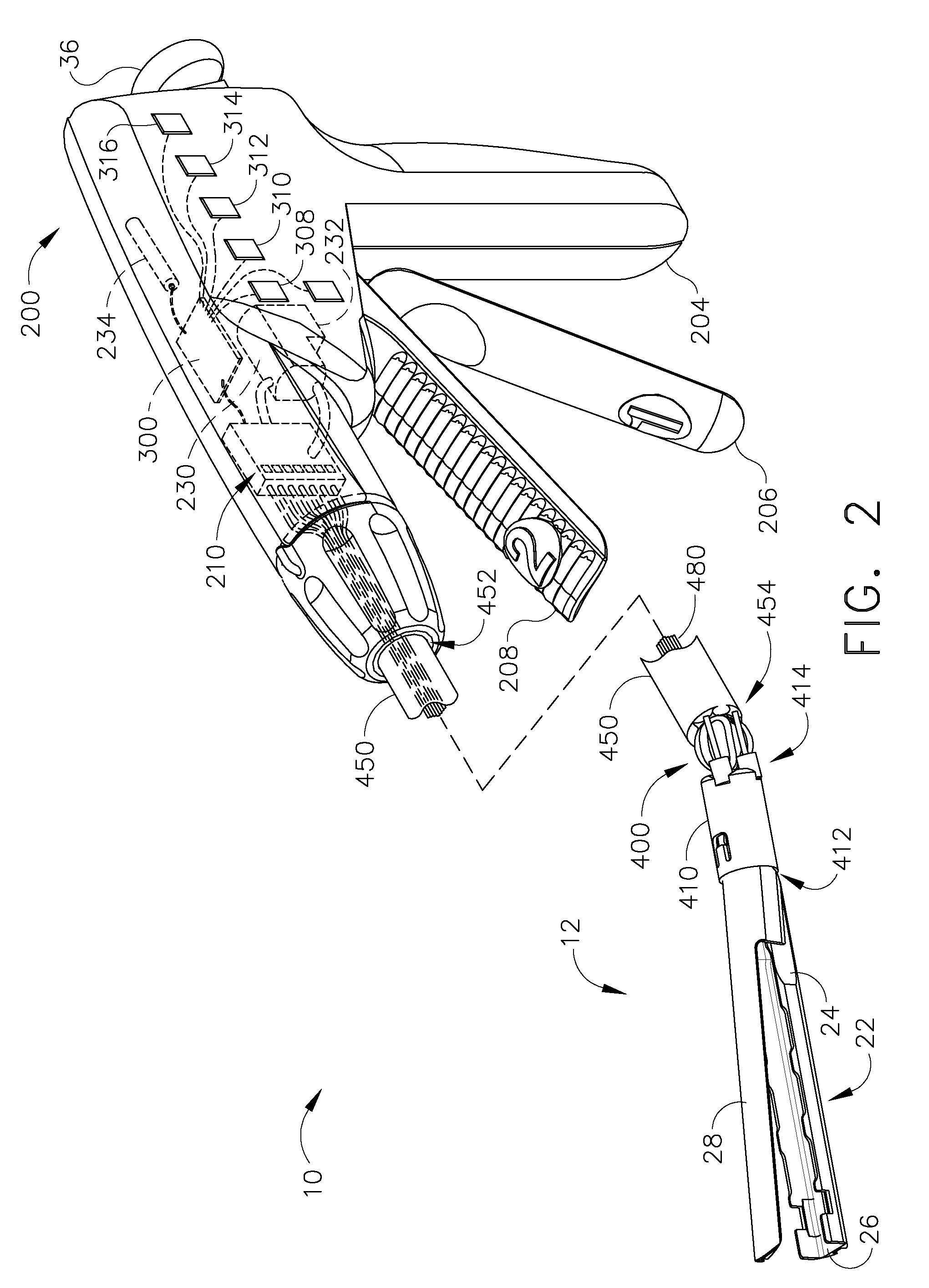
[0034]Turning to the Figures, wherein like numerals denote like components throughout the several views, FIGS. 1 and 2 depict one embodiment of a surgical instrument 10 that is capable of practicing the unique benefits of the present invention. As can be seen in FIGS. 1 and 2, the instrument 10 includes a handle assembly 200 and a surgical implement portion 12. As used herein, the term “surgical implement” refers to a component or set of components configured to engage tissue to accomplish a surgical task. Examples of surgical implements include, but are not limited to: endocutters, graspers, clamps, cutters, staplers, clip appliers, probes or access devices, drug / gene therapy delivery devices, energy devices such as ultrasound, RF, or laser devices, etc.

[0035]In the non-limiting embodiment depicted in the Figures, the surgical instrument 10 includes a hydraulically actuated end effector 22 and handle arrangement 200 of the type disclosed in the U.S. patent application Ser. No. 11 / 2...


PUM


Abstract

Articulation joints for use in connection with a surgical instrument that has a portion that must be passed through a trocar or similar structure and then articulated relative to another portion of the instrument received within the trocar. Various embodiments of the articulation joint include at least one flexible driven member to articulate the surgical implement relative to the handle assembly of the instrument.

Description

CROSS-REFERENCE TO RELATED APPLICATIONS[0001]This non-provisional application for patent is a divisional patent application of U.S. patent application Ser. No. 11 / 270,866, filed Nov. 9, 2005, the disclosure of which is herein incorporated by reference in its entirety.FIELD OF THE INVENTION[0002]The present invention relates in general to surgical instruments that are suitable for endoscopically inserting an end effector (e.g., endocutter, grasper, cutter, staplers clip applier, access device, drug / gene therapy delivery device, an energy device using ultrasound, RF, laser, etc.) and, more particularly, to endocutters with articulating end effectors.BACKGROUND OF THE INVENTION[0003]Endoscopic surgical instruments are often preferred over traditional open surgical devices since a smaller incision tends to reduce the post-operative recovery time and complications. Generally, these endoscopic surgical instruments include an “end effector”, a handle assembly and a long shaft that extends ...

Claims


Application Information

Patent Timeline
Patent Type & Authority Applications(United States)
IPC IPC(8): A61B1/00
CPCA61B17/07207A61B17/29A61B2017/00017A61B2017/003A61B2017/00367A61B2017/00398A61B17/3205A61B2017/2901A61B2017/2925A61B2017/2927A61B17/068A61B17/105A61B2017/00535A61B2017/07285A61B17/0644A61B17/072A61B2017/07242A61B2017/07257A61B2017/07271A61B2017/0645
Inventor SHELTON, IV, FREDERICK E.SWAYZE, JEFFREY S.
Owner CILAG GMBH INT
Why Eureka
Try Eureka