Display and input device and method for manufacturing the same

Inactive Publication Date: 2010-07-22
MITSUBISHI ELECTRIC CORP
View PDF0 Cites 14 Cited by
  • Summary
  • Abstract
  • Description
  • Claims
  • Application Information

AI Technical Summary

Benefits of technology

[0011]An advantage of the present invention is to provide a display and input device that includes an optically transparent substrate, such as a touch panel, attached on the display surface of a display element and can accurately align the display element and the optically transparent substrate without increasing manufacturing process steps, and a method for manufacturing the same.
[0012]A first exemplary aspect of the present invention is a display and input device that includes a display element, a frame having a rectangular opening for holding the display element, and an optically transparent substrate disposed as opposed to the frame, wherein an alignment mark is placed on the substrate in a manner corresponding to the opening of the optically transparent frame.
[0013]A second exemplary aspect of the present invention is a method for manufacturing a display and input device that includes a display element, a frame having a rectangular opening for holding the display element, and an optically transparent substrate disposed as opposed to the frame. The method includes steps of aligning an alignment mark placed on the optically transparent substrate with the opening of the frame or an alignment mark placed on the frame, and attaching the optically transparent substrate to the frame.
[0014]According to the exemplary aspects of the present invention described above, it is possible to provide a display and input device that includes an optically transparent substrate attached on the display surface of a display element and a method for manufacturing the same which enable accurately align the display element and the optically transparent substrate without increasing manufacturing process steps.

Problems solved by technology

On the other hand, display and input devices as described above have a problem that inaccurate attaching of a touch panel on a display device hampers accurate input operations.
However, we have now discovered that the alignment mark is difficult to recognize as an image, since it is formed of the transparent material.
Also, an apparatus is required to provide signals to the display element to display the alignment pattern, resulting in complication of the manufacturing process.
Also, after attaching the touch panel, whether it is attached on a predetermined position accurately cannot be checked visually.

Method used


Image

  • Display and input device and method for manufacturing the same
  • Display and input device and method for manufacturing the same
  • Display and input device and method for manufacturing the same

Examples


first exemplary embodiment

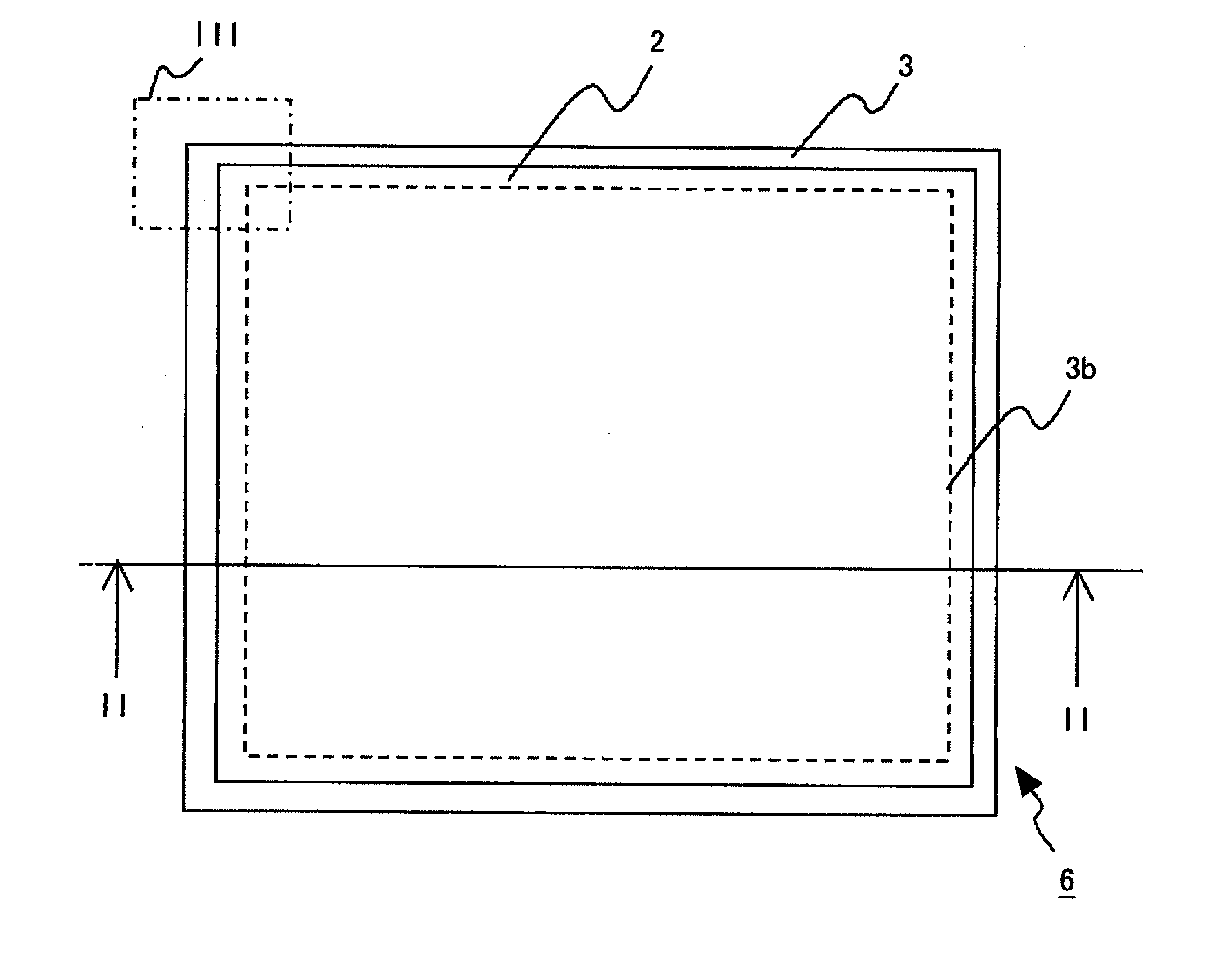
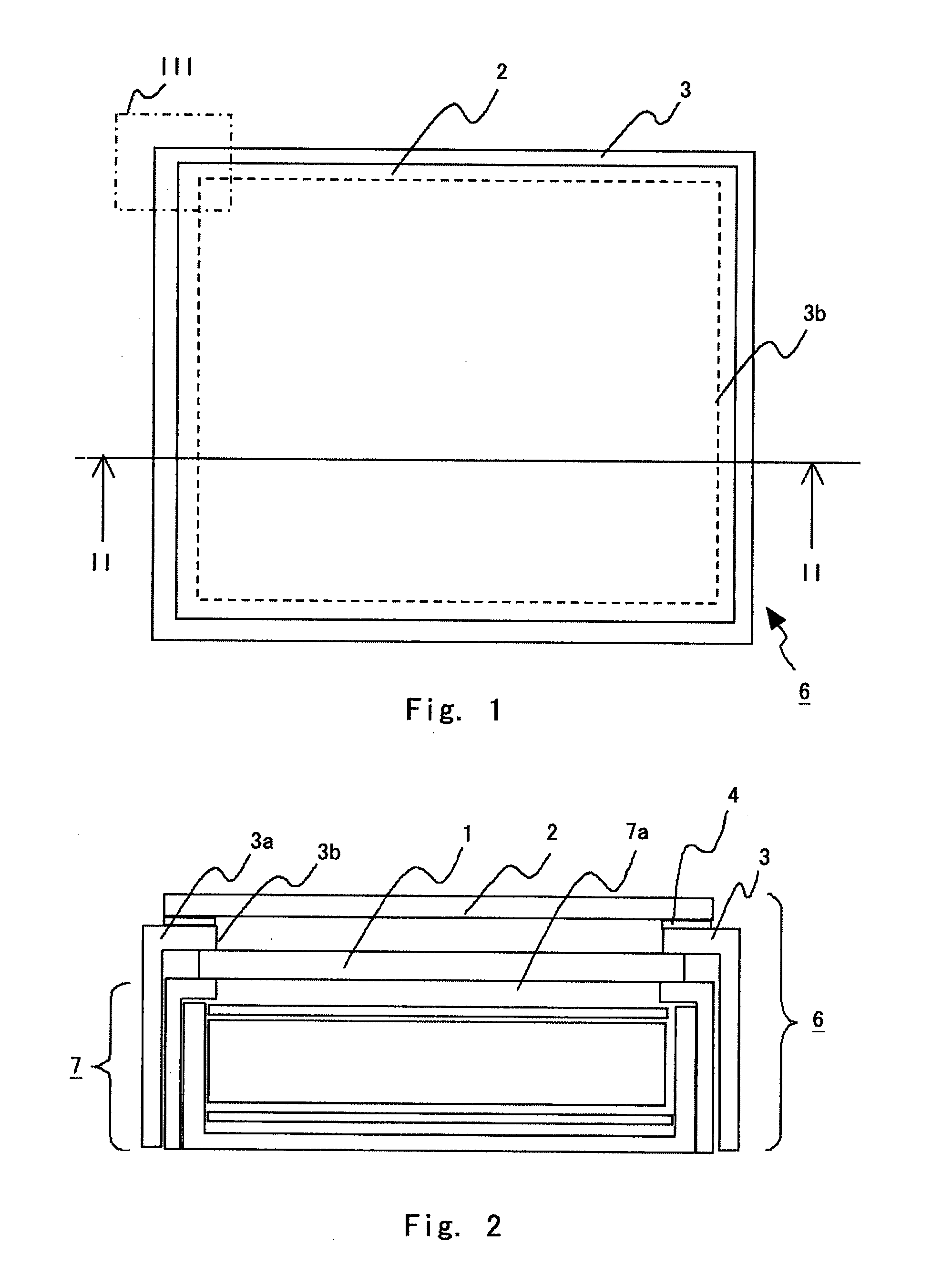
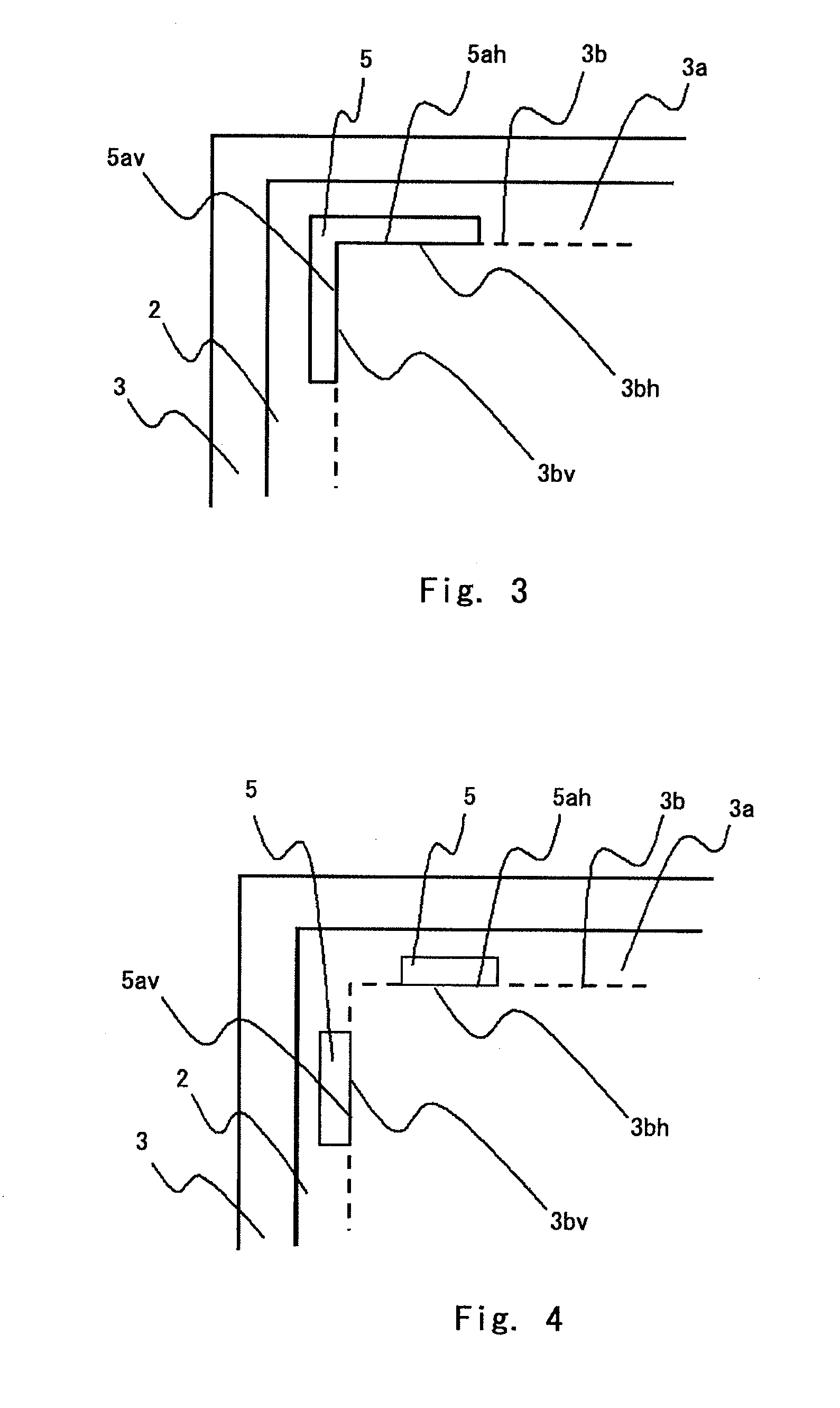
[0024]Now, a display and input device according to a first exemplary embodiment of the present invention will be described with reference to the accompanying drawings. FIG. 1 is a top view showing a state in which an optically transparent substrate such as a touch panel is disposed on a display device. FIG. 2 is a sectional view as seen in the direction of arrows II-II of FIG. 1. FIG. 3 is an enlarged view of a III part of FIG. 1. As shown in FIGS. 1 and 2, a display and input device 6 includes a backlight 7, a display element 1 that receives light from the backlight 7 via the back surface thereof, and a touch panel 2 that is an optically transparent substrate and is disposed as opposed to the display element 1. The display element 1 such as a liquid crystal panel is disposed as opposed to a light emitting surface 7a of the backlight 7. A frame 3 has a rectangular opening 3b on an upper part 3a thereof and holds the display element 1 and the backlight 7. The touch panel 2 is attache...

second exemplary embodiment

[0029]FIG. 6 shows an enlarged view of a major part of a second exemplary embodiment of the present invention. In the first exemplary embodiment, the alignment mark is placed on the position adjacent to one corner of the opening 3b of the frame 3, of the touch panel 2. On the other hand, in the second exemplary embodiment, an alignment mark 53 is placed adjacent to edges of the touch panel 2 and an alignment mark 31 is placed on a position corresponding to the alignment mark 53, of the upper part 3a of the frame 3. The alignment mark 31 may be formed on the frame 3 during the process of performing pressing or the like on the frame 3. The alignment mark 31 is formed using an inscription, such a scribed line, printing, or the like. By aligning the alignment mark 53 placed on the touch panel 2 with the alignment mark 31 placed on the frame 3, the touch panel 2 can be attached on a desired position of the frame 3. The alignment mark 53 placed adjacent to the edges of the touch panel 2 h...

third exemplary embodiment

[0030]FIG. 7 is a drawing showing a third exemplary embodiment of the present invention. FIG. 8 is an enlarged view of a VIII part of FIG. 7. In the first exemplary embodiment, the alignment mark is placed in a manner corresponding to at least the horizontal and vertical edges of the opening 3b of the frame 3. On the other hand, in order to attach the touch panel and frame together more accurately using an apparatus, alignment marks as shown in FIGS. 7 and 8 may be placed. In FIG. 8, a cross-shaped alignment mark 54 is placed adjacent to edges of the touch panel 2. Also, four rectangular alignment marks 32 to form a rectangle with the cross-shaped alignment mark 54 are placed on the upper part 3a of the frame 3, on which the touch panel 2 is to be attached. By reading the alignment marks 32 and the alignment mark 54 using an image processing device and positioning the touch panel 2 and frame 3 using an automatic machine, the touch panel 2 can be attached more accurately than attache...


PUM


Abstract

An alignment mark is placed in a position adjacent to at least one of the four corners of an opening of a frame, of a touch panel in a manner corresponding to edges of the opening of the frame. The alignment mark placed on the touch panel is aligned with the edges of the opening made on the upper part of the frame. This allows accurate aligning of the touch panel on the display element.

Description

INCORPORATION BY REFERENCE[0001]This application is based upon and claims the benefit of priority from Japanese patent application No. 2009-010858, filed on Jan. 21, 2009, the disclosure of which is incorporated herein in its entirety by reference.BACKGROUND OF THE INVENTION[0002]1. Field of the Invention[0003]The present invention relates to a display and input device and method for manufacturing the same. Particularly, present invention relates to a display and input device that includes an optically transparent substrate attached on the display surface of a display element, and method for manufacturing the same.[0004]2. Description of Related Art[0005]Display and input devices where a touch panel is attached on the display surface of a display device have been widely used in recent years. Typical examples thereof include mobile terminals and automatic teller machines (ATMs) for banks. Among major industrial applications thereof are operation panels of apparatuses. One of the reas...

Claims


Application Information

Patent Timeline
IPC IPC(8): H05K5/00
CPCG06F3/041G06F1/1601
Inventor ARITA, KENJI
Owner MITSUBISHI ELECTRIC CORP
Why Eureka
Try Eureka