Protective headgear compression member

Inactive Publication Date: 2010-07-29
XENITH
View PDF18 Cites 112 Cited by
  • Summary
  • Abstract
  • Description
  • Claims
  • Application Information

AI Technical Summary

Benefits of technology

[0015]Preferably, the bottom wall of the cell inboard the cell flange is curved upwardly, giving the cell a dished or concave undersurface to provide additional clearance for the pad(s). This construction along with the pad(s) enables the compression member to withstand appreciable compression forces

Problems solved by technology

Head injury can result from impact forces due to contact with other people or objects.
Also, the compressible structures forming the dynamic inner liner of the helmet are usually simply foam pads or capsules adhered to the underside of the associated cell and are pro

Method used


Image

  • Protective headgear compression member
  • Protective headgear compression member
  • Protective headgear compression member

Examples


Example

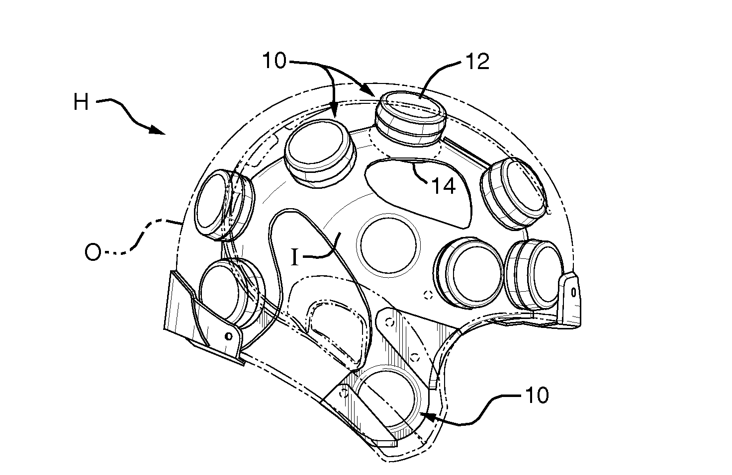
[0021]Referring to FIG. 1 of the drawings, compression members incorporating the invention and indicated generally at 10 are shown incorporated into a protective structure, i.e., a football helmet H having an outer layer or shell shown in phantom at O and an inner layer I. Members 10 are releasably secured to layer I. As described in the above publications, shell O is of a relatively hard plastic material that deforms locally and radially in response to an impact, and the inner layer I may be of a softer, less rigid material.

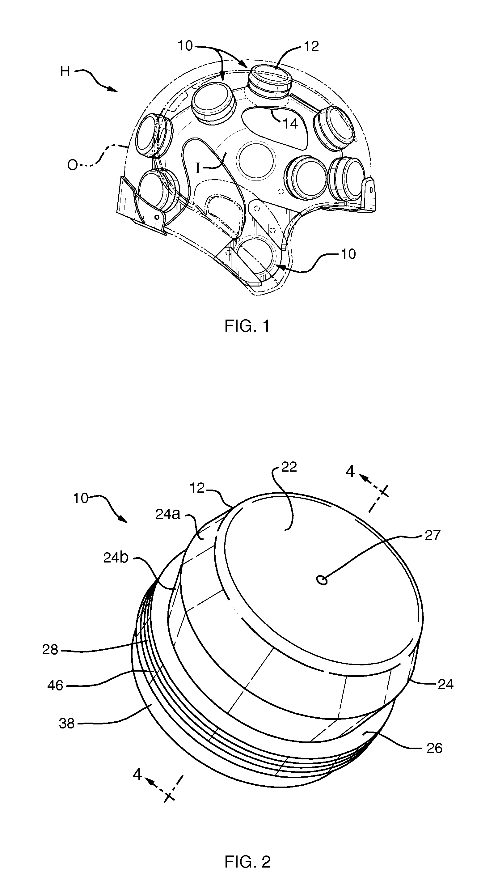
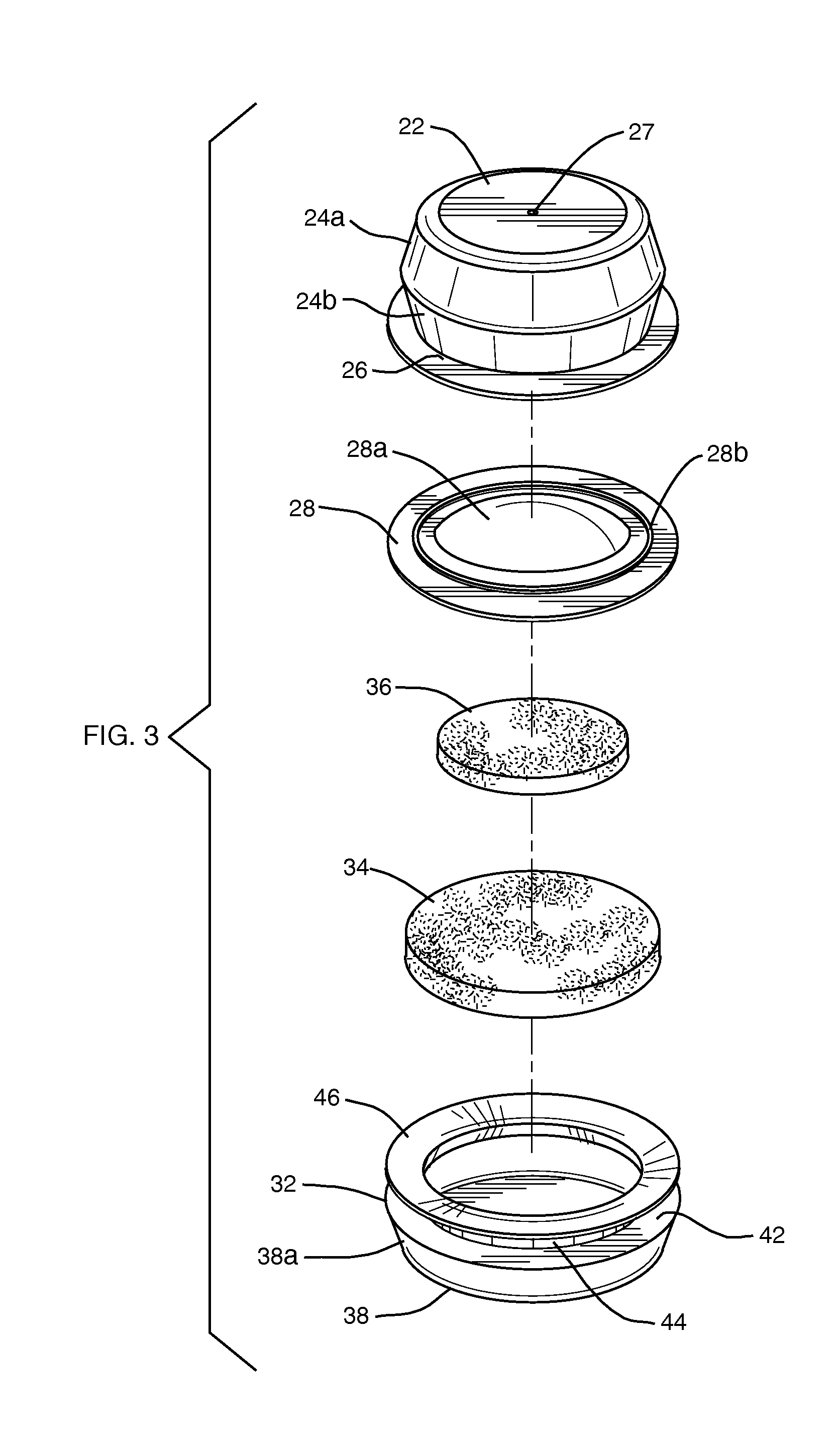
[0022]Each compression member 10 comprises a hollow, compressible, resilient cell 12 which extends between the inner and outer layers, and a compressible liner element 14 located directly opposite cell 12 and which projects from the interior surface of layer I. Cells 12 collectively form a helmet middle layer in an interstitial region between layers O and I and elements 14 collectively form a dynamic inner liner of the helmet.

[0023]As shown in FIG. 4, each membe...


PUM


Abstract

A protective headgear compression member includes a hollow compression cell having a top wall, a bowed side wall and a bottom wall and a liner element secured to that bottom wall coaxially to said cell. The liner element is composed of a flexible envelope substantially filled with resilient material and the envelope is secured to the bottom wall via an axially flexible connection to prevent the bottoming out of the liner element against the bottom wall of the cell.

Description

BACKGROUND OF THE INVENTION[0001]1. Field of the Invention[0002]This invention relates to protective headgear and other impact absorbing structures. It relates especially to an impact absorbing compression member for use therein.[0003]2. Background Information[0004]Headgear such as a helmet is often worn by individuals during games and other physical activities to help protect the wearers from head injury. Head injury can result from impact forces due to contact with other people or objects. Currently marketed helmets generally fall into one of two categories, i.e. single impact helmets or multiple impact helmets. Single impact helmets undergo permanent deformation under impact, whereas multiple impact helmets are capable of withstanding multiple blows. The wearers of single impact helmets include, for example, bicyclists and motorcyclists. On the other hand, participants in sports such as hockey and football and construction workers generally wear multiple impact helmets. Both cate...

Claims


Application Information

Patent Timeline
IPC IPC(8): A42B3/00
CPCA42B3/128F16F9/0481F16F13/002A42B3/121
Inventor FERRARA, VINCENT R.HIBCHEN, KURT
Owner XENITH
Why Eureka
Try Eureka