This helps you quickly interpret patents by identifying the three key elements:
Problems solved by technology
Method used
Benefits of technology
[0009]The present invention will become more obvious from the following description when taken in connection with the accompanying drawings which show, for purposes of illustration only, a preferred embodiment in accordance with the present invention.
Problems solved by technology
Due to the weight, the cable management arm and the cables tend to droop over a certain period of time to negatively affect the operation in a highly intensively slide-in space due to the mass of the cable and the cable management arm.
Method used
Image
Click on the blue label to locate the original text in one second.
Reading with bidirectional positioning of images and text.
Examples
Embodiment Construction
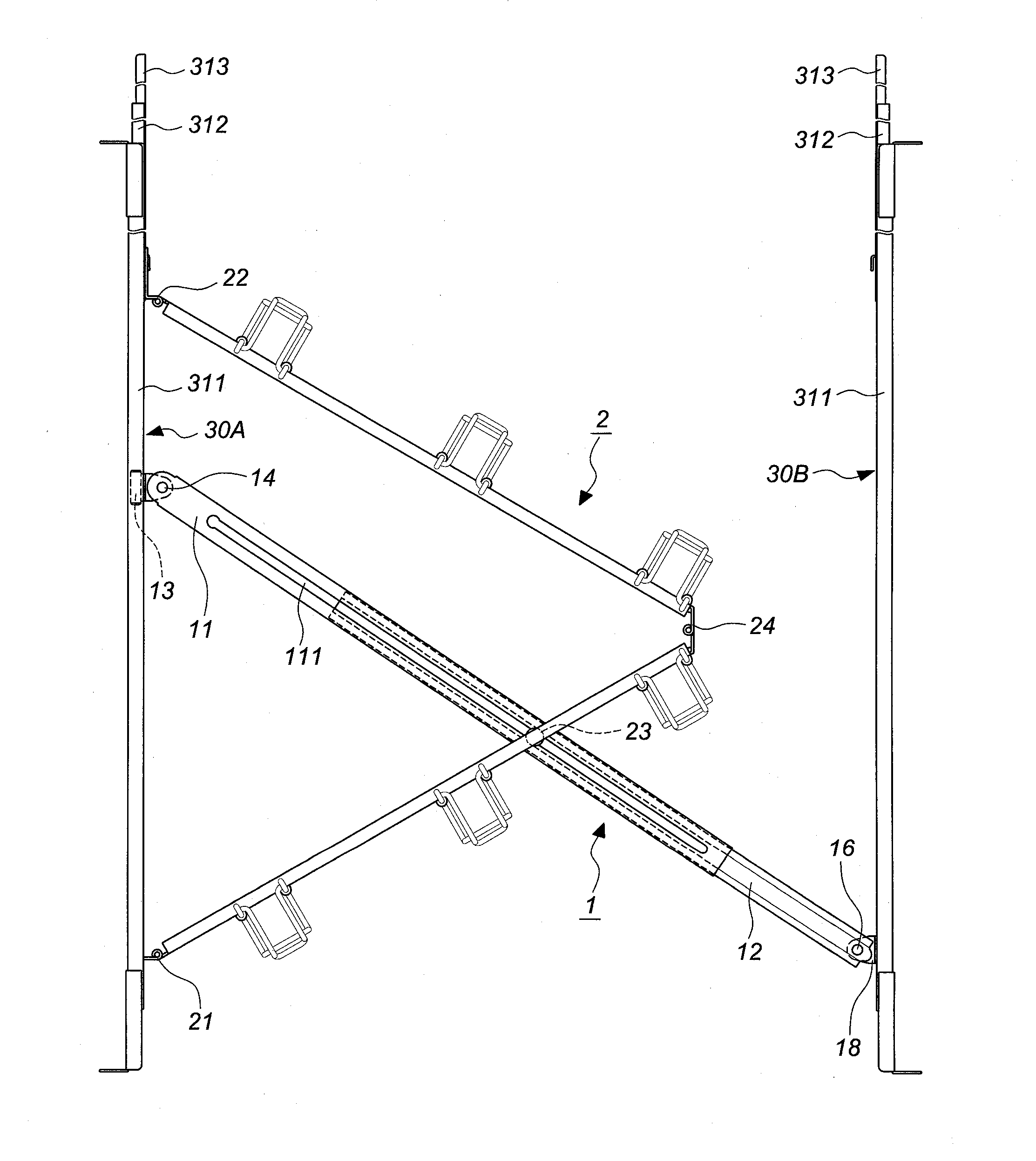
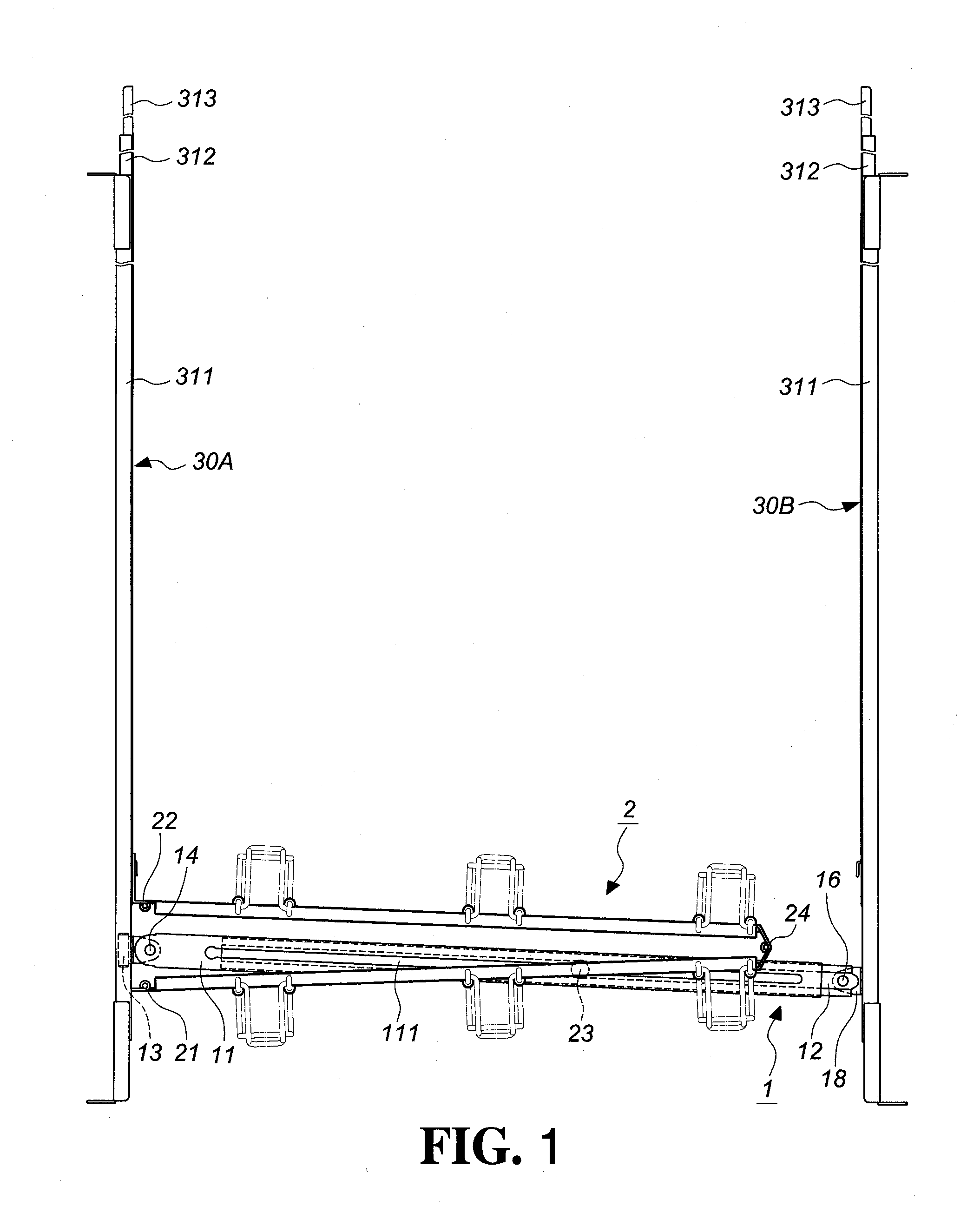
[0015]Referring to FIG. 1, the present invention comprises a support slide rail 1, a cable management arm 2 including a first pivot member 21 and a second pivot member 22, and a first slide assembly 30A and a second slide assembly 30B. Each of the first and second slide assemblies 30A, 30B includes a first slide rail 311, a second slide rail 312 slidably connected to the first slide rail 311, and a third slide rail 313 slidably connected to the second slide rail 312. The cable management arm 2 has the first pivot member 21 thereof connected to the first slide rail 311 of the first slide assembly 30A and the second pivot member 22 of the cable management arm 2 is connected to the third slide rail 313 of the first slide assembly 30A.
[0016]A third pivot member 24 is located between the first pivot member 21 and the second pivot member 22 of the cable management arm 2, so that the first pivot member 21 and the second pivot member 22 can be moved away from each other or toward each other...
PUM
Abstract
A support slide assembly for a cable management arm includes first and second slide assemblies. The cable management arm is connected between the two slide rails of the first slide assembly. A third pivot member and a sliding member are located between first and second pivot members on two ends of the cable management arm. Two ends of a support slide rail are connected to the first and second slide assemblies respectively. The support rail is retractable by the slidable first and second rods. The first rod has one end pivotably connected to a sliding block which is slidably connected to the first slide assembly. The second rod has one end pivotably connected to the second slide assembly. The sliding member is slidably connected to the support slide rail. When the first slide assembly pulls the cable management arm out, the first and second rods extend relative to each other and form an angle relative to the first and second slide assemblies.
Description
[0001]The present invention is a Continuation-In-Part application of U.S. patent application Ser. No. 12 / 230,646, filed on Sep. 3, 2008, currently pending, and U.S. patent application Ser. No. 12 / 324,968, filed on Nov. 28, 2008, currently pending. The length of the support slide assembly is adjustable. The support slide assembly has one end pivotably connected to the slide rail and the other end is slidably connected to another slide rail by a sliding block, such that the length of the support slide assembly can be automatically adjusted.FIELD OF THE INVENTIONBackground of the Invention[0002]A conventional electronic product, such as a server, mounted on a slide-in chassis, is provided with two slides on both sides thereof so that the electronic product slides to travel on both slides. A cable management arm to contain and restrict the cable.[0003]As disclosed in U.S. Pat. Nos. 4,353,518, 4,614,383, 5,571,256, 6,303,864B1, 6,305,556B1, 6,442,030B1, 6,600,665B1, and US Patent Applica...
Claims
Application Information
Patent Timeline
Application Date:The date an application was filed.
Publication Date:The date a patent or application was officially published.
First Publication Date:The earliest publication date of a patent with the same application number.
Issue Date:Publication date of the patent grant document.
PCT Entry Date:The Entry date of PCT National Phase.
Estimated Expiry Date:The statutory expiry date of a patent right according to the Patent Law, and it is the longest term of protection that the patent right can achieve without the termination of the patent right due to other reasons(Term extension factor has been taken into account ).
Invalid Date:Actual expiry date is based on effective date or publication date of legal transaction data of invalid patent.
Patent Type & Authority Applications(United States)