Light emitting diode (LED) arrangement with bypass driving

a technology of leds and diodes, which is applied in the direction of cathode-ray/electron beam tube circuit elements, instruments, lighting and heating apparatus, etc., can solve the problems of high voltage over the series-connected leds in the led segment, severe damage to the leds, etc., to power the driver

Active Publication Date: 2010-08-05
NXP BV
View PDF17 Cites 109 Cited by
  • Summary
  • Abstract
  • Description
  • Claims
  • Application Information

AI Technical Summary

Benefits of technology

[0005]The present invention aims to provide a LED arrangement comprising a LED string and a driver circuit arrangement which can accommodate a wide range of duty cycles for driving each individual LED or each individual segment of several LEDs with bypass switches without the occurrence of current spikes, which could damage the LEDs. The invention further aims to provide a LED assembly to be applied in such a LED arrangement.

Problems solved by technology

These high transient current peaks could severely damage the LEDs.
The voltage over the series-connected LEDs in the LED segment may be too high in order to power the driver.

Method used


Image

  • Light emitting diode (LED) arrangement with bypass driving
  • Light emitting diode (LED) arrangement with bypass driving
  • Light emitting diode (LED) arrangement with bypass driving

Examples


Embodiment Construction

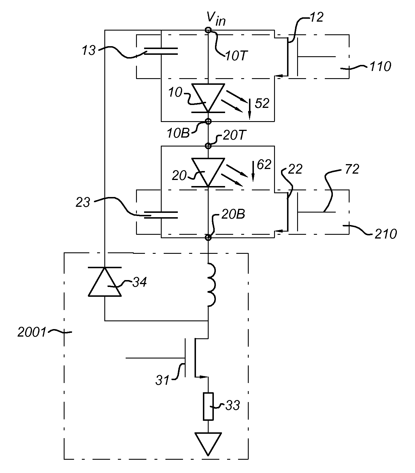
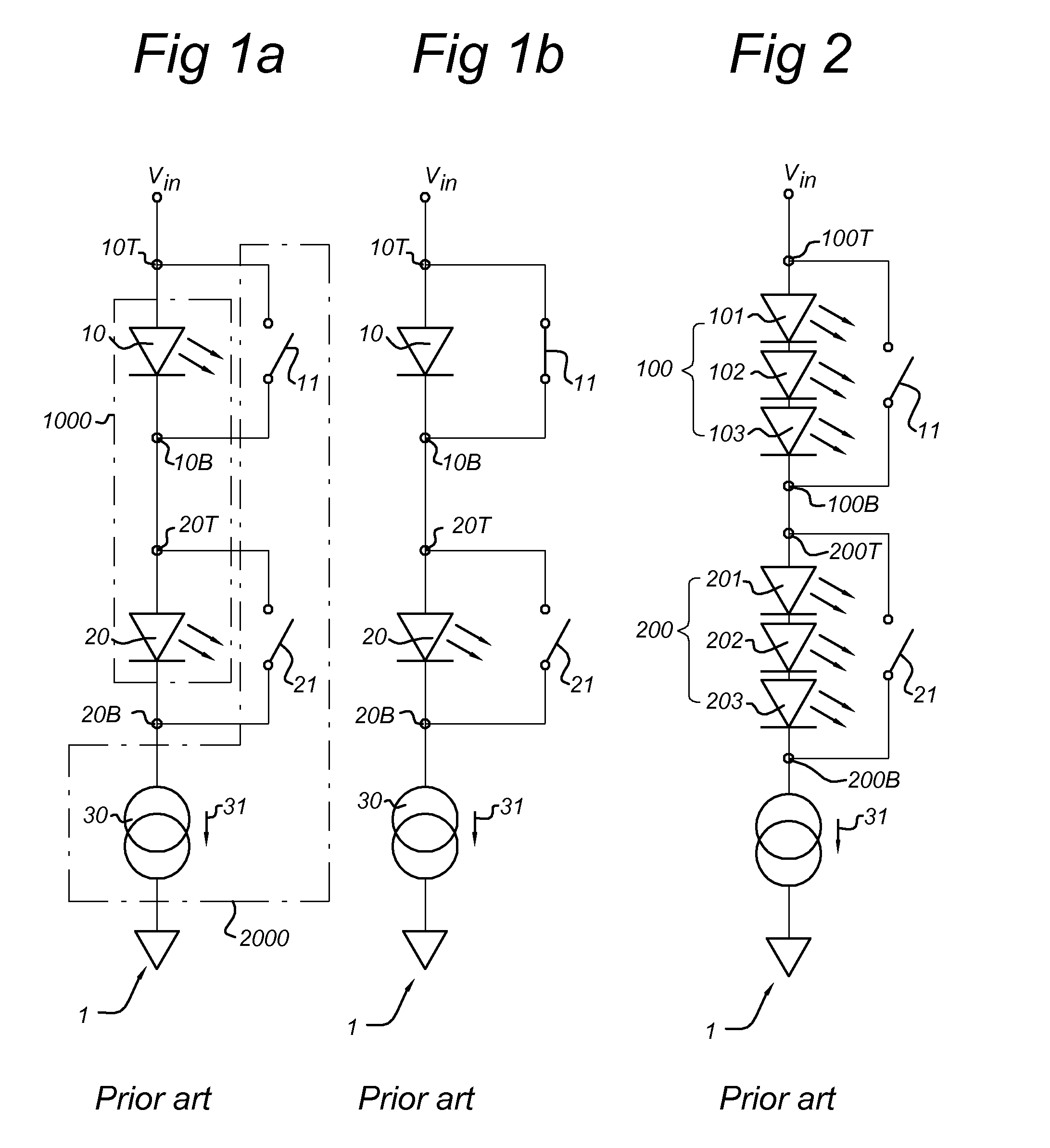
[0083]FIG. 1a shows a number of LEDs 10, 20 arranged electrically in series forming a LED string 1000. The LED string is equipped with a driver circuit 2000. The driver circuit comprises a current source 30 which supplies a current 31, electrical switches 11, 21 and nodes 10T, 10B, 20T and 20B. The switches 11, 21 are each arranged electrically parallel with a LED 10, 20. The switch 11 connects between node 10T and 10B on either side of LED 10. Likewise, the switch 21 connects between node 20T and 20B on either side of LED 20. When the switches 11, 21 are open, the current 31 flows through the LEDs 10, 20, causing the LEDs to emit light, as shown in FIG 1a. FIG. 1b shows the same arrangement, but with the top switch 11 closed. This gives a lower-resistive current path through the top switch 11 as through the top LED 10, causing the current to flow through the top switch 11 instead of the top LED 10, and thus causing the top LED 10 to switch off. The current is thus bypassing the LED...


PUM


Abstract

The invention provides a LED arrangement including a LED string of a series arrangement of LED segments. A LED segment includes a single LED or a series arrangement of LEDs. A switching element (12, 22) is arranged in parallel with each corresponding LED segment (10, 20) of the LED string, for controlling a current (52, 62) through the LED segment (10, 20). A capacitor (13, 23) is arranged in parallel with each corresponding LED segment (10, 20) in order to prevent the occurrence of possibly harmful current spikes while switching one or more LED segments. The LED arrangement may also include a switched-mode power supply (2001). The invention further provides a LED assembly. A plurality of such LED assemblies assembles easily into a LED arrangement according to the invention.

Description

FIELD OF THE INVENTION[0001]The invention relates to a light emitting diode (LED) arrangement. The invention further relates to a LED assembly. The invention further relates to an illumination system.BACKGROUND OF THE INVENTION[0002]Such a LED arrangement is known from U.S. Pat. No. 5,959,413. U.S. Pat. No. 5,959,413 discloses a driving circuit in which each LED has a controllable logic switch in parallel across it and the switches are further in series circuit with each other to form a ladder network. Any selected LED may be switched off by closing its corresponding switch. The current continues to flow then through the shunting switch into the remaining LEDs in the series circuit that are on. A plurality of such ladder networks may be coupled in parallel with each other and each ladder network may be controlled by a switching gate which selectively couples it to the constant current source so that the LED ladder networks are operated at a predetermined duty cycle. Current spikes a...

Claims


Application Information

Patent Timeline
Patent Type & Authority Applications(United States)
IPC IPC(8): H05B37/02H05B44/00
CPCH05B33/0803H05B33/083H05B33/0818H05B45/48H05B45/3725H05B45/30
Inventor HOOGZAAD, GIAN
Owner NXP BV
Why Eureka
Try Eureka