Beam spreading optics for light emitting diodes

a technology of light-emitting diodes and beam spreading optics, which is applied in the direction of instruments, discharge tubes, luminescnet screens, etc., can solve the problems of falling off of relative power, complicated mounting arrangements, and time-consuming and labor-intensive problems

Active Publication Date: 2010-08-05
ABL IP HLDG
View PDF20 Cites 123 Cited by
  • Summary
  • Abstract
  • Description
  • Claims
  • Application Information

AI Technical Summary

Benefits of technology

[0040]FIG. 13 is a schematic drawing of the lens and control electronics, overlaid with a dimensioned drawing of an exemplary volume envelope for an incandescent fixture.

Problems solved by technology

For angles outside this range, there is some falloff of the relative power, caused by a shadowing from the threaded stem of the bulb.
There area several drawbacks to mounting the LEDs on a non-planar surface.
First, such a mounting arrangement is complicated, time- and labor-intensive, and expensive.
Second, such a mounting arrangement cannot use standard, off-the-shelf LED packages.
Both of these drawbacks make the CAO Group approach less than optimal.
A potential drawback to the device of Mi{umlaut over (n)}ano is that it is quite large, and has a significant longitudinal extent beyond the LED chips.
While such a device may be suitable for a flashlight, which already has a natural longitudinal shape, such a device may not be suitable for an incandescent-bulb replacement, which may fit in a much smaller spatial envelope.

Method used


Image

  • Beam spreading optics for light emitting diodes
  • Beam spreading optics for light emitting diodes
  • Beam spreading optics for light emitting diodes

Examples


Embodiment Construction

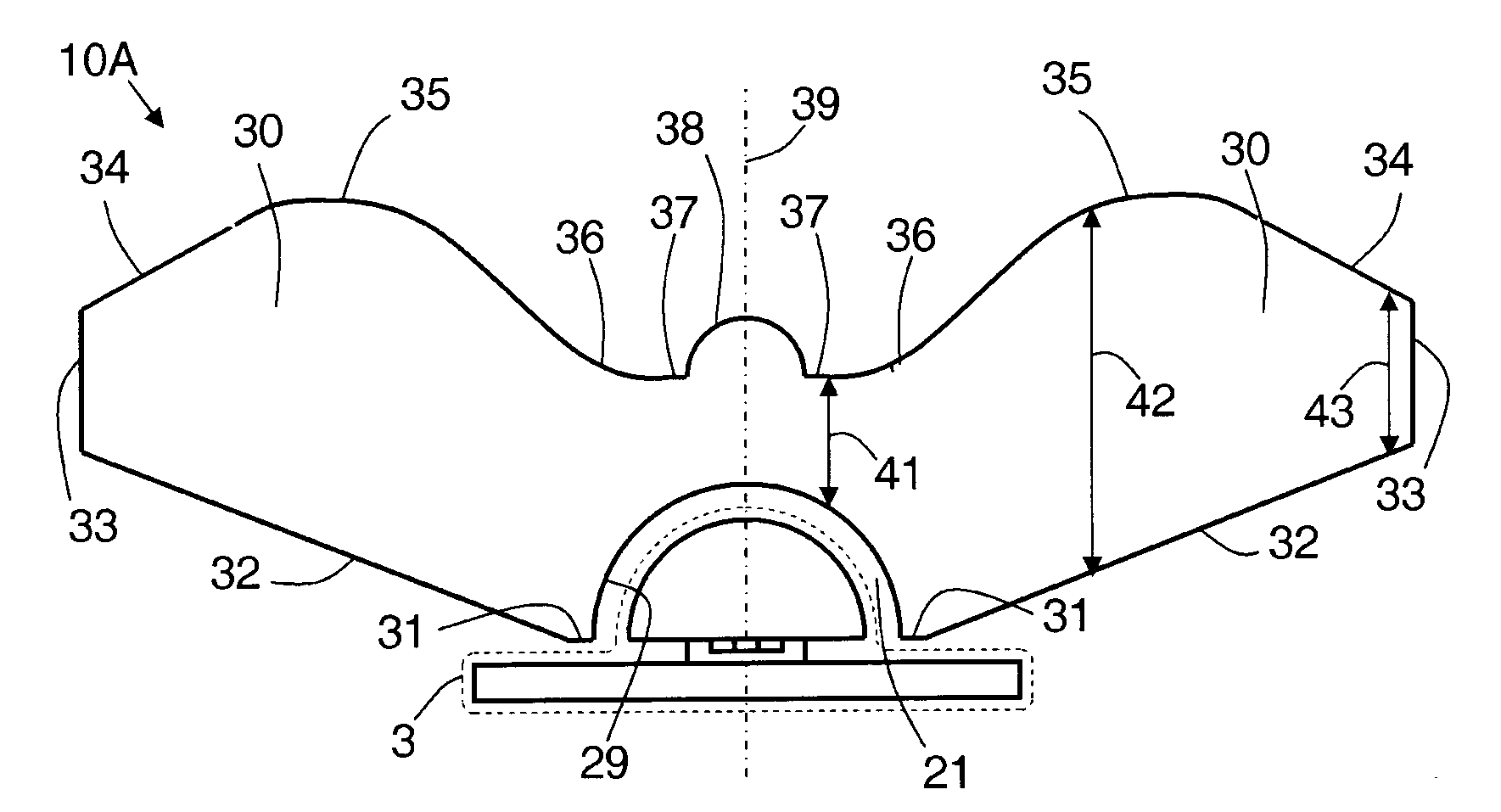
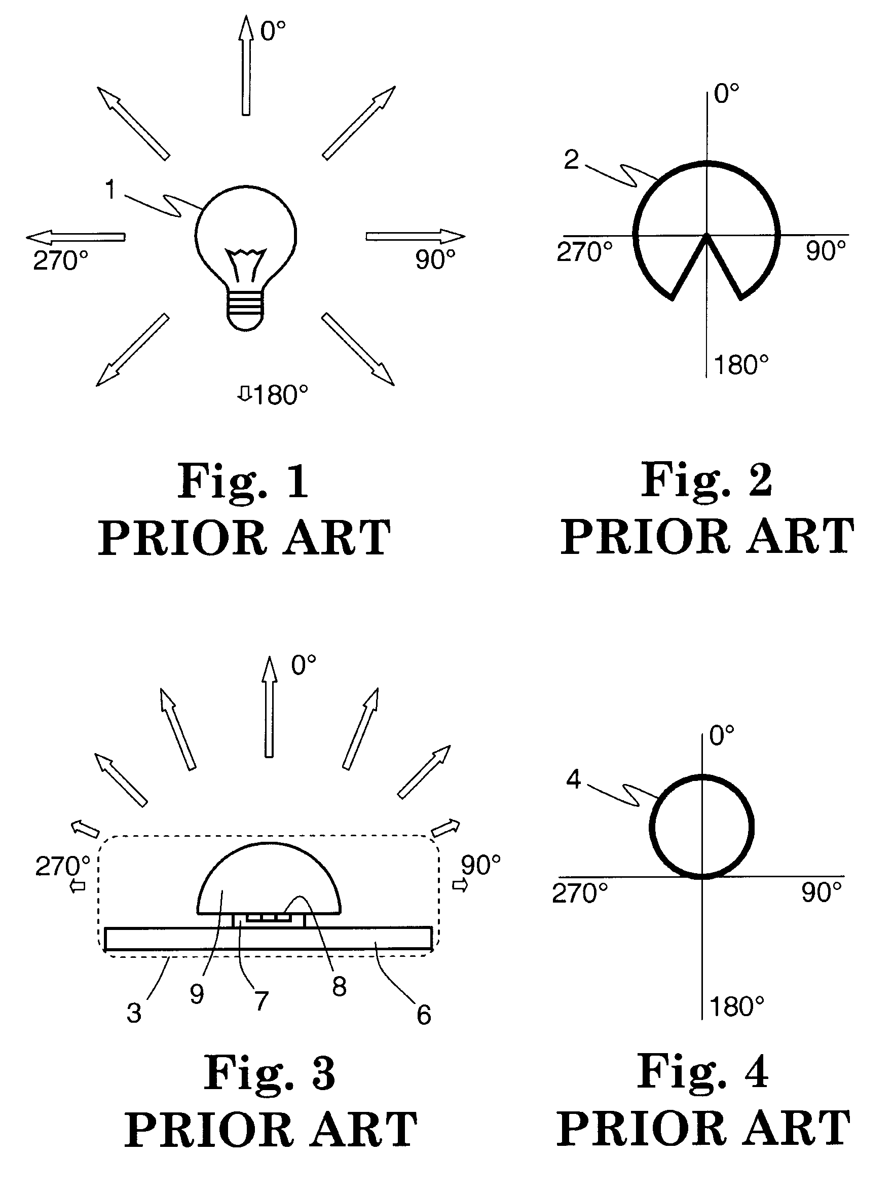
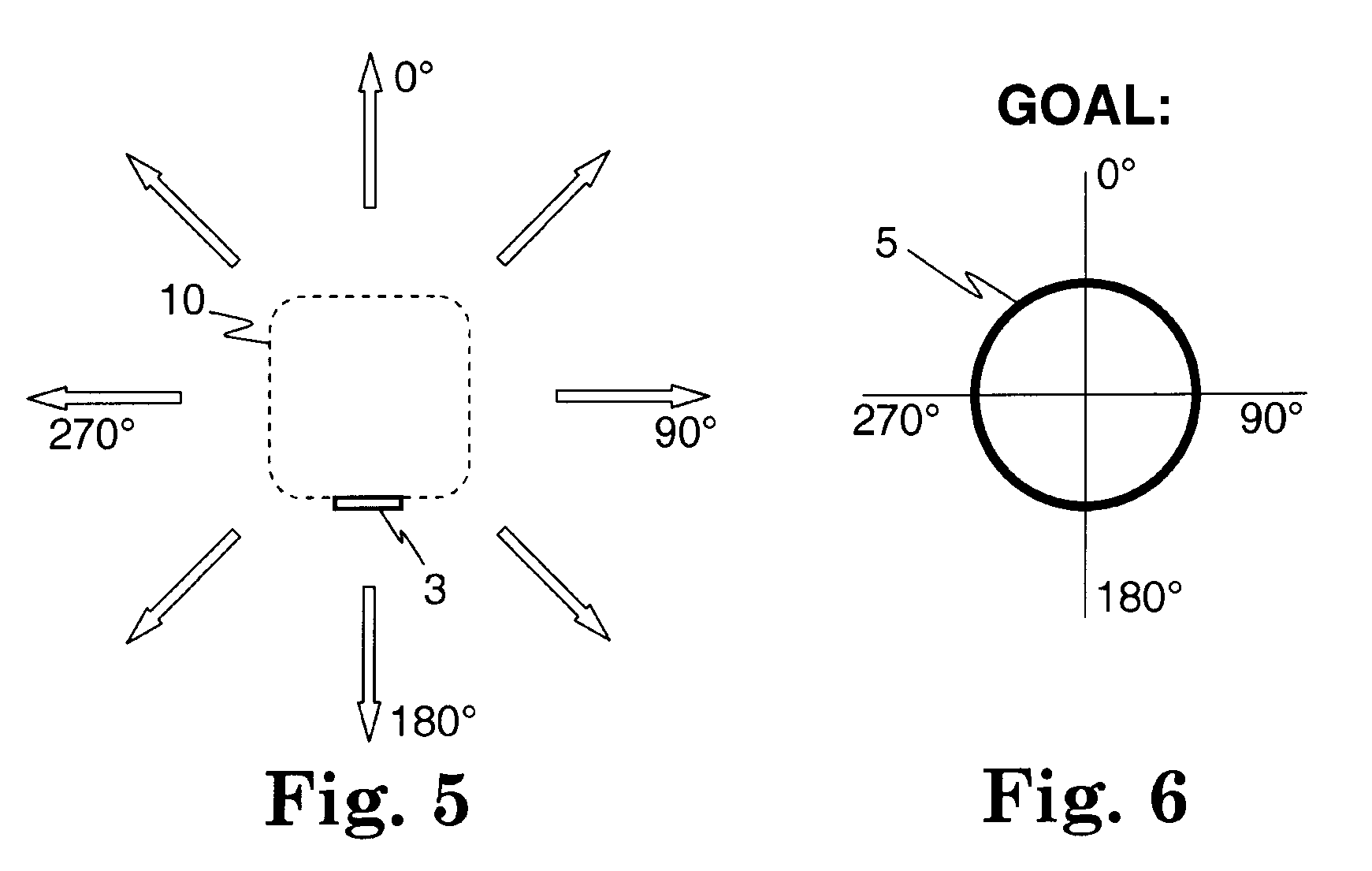
[0041]An optical element is disclosed, for receiving relatively narrow light from a planar light-emitting diode (LED) source, and for redistributing the light into a relatively wide range of output angles that span a full 360 degrees. The element may be used to retrofit existing fixtures that were originally designed for incandescent bulbs with LED-based light sources that have similar emission profiles. The element is small enough so that it may be packaged along with an LED module and its control electronics in the volume envelope of an incandescent light bulb. An exemplary element is a single, transparent, rotationally-symmetric lens that has a batwing shape in cross-section, extending angularly away from a longitudinal axis. The lens also includes a variety of curved, straight, specular and, optionally, diffuse portions on its longitudinal and transverse faces, all of which cause a variety of internal and external reflections, refractions, and, optionally, scattering. As such, m...


PUM


Abstract

An optical element is disclosed, for receiving relatively narrow light from a planar light-emitting diode (LED) source, and for redistributing the light into a relatively wide range of output angles that span a full 360 degrees. The element may be used to retrofit existing fixtures that were originally designed for incandescent bulbs with LED-based light sources that have similar emission profiles. The element is small enough so that it may be packaged along with an LED module and its control electronics in the volume envelope of an incandescent light bulb. An exemplary element is a single, transparent, rotationally-symmetric lens that has a batwing shape in cross-section, extending angularly away from a longitudinal axis. The lens also includes a variety of curved, straight, specular and optionally diffuse portions on its longitudinal and transverse faces, all of which cause a variety of internal and external reflections, refractions, and optionally scattering. As such, many of the specific lens features cannot be directly linked to specific optical effects at a particular angle; rather, the features all interact with each other to produce the wide-angle light output.

Description

CROSS-REFERENCE TO RELATED APPLICATIONS[0001]Not ApplicableSTATEMENT REGARDING FEDERALLY SPONSORED RESEARCH OR DEVELOPMENT[0002]Not ApplicableBACKGROUND OF THE INVENTION[0003]1. Field of the Invention[0004]The present invention is directed to an optical element for receiving relatively narrow light from a planar light-emitting diode (LED) source, and for redistributing the light into a relatively wide range of output angles that span a full 360 degrees.[0005]2. Description of the Related Art[0006]Light emitting diodes (LEDs) are rapidly finding acceptance in many lighting applications. Compared with incandescent light bulbs, LEDs are more efficient, have longer lifetimes, and may be packaged in a wide variety of suitably shaped and sized packages.[0007]The cone of light emerging from a typical LED is rather narrow. While this may be a desirable characteristic for some applications, such as spotlights, there are other applications where it may be desirable to have a wider angular out...

Claims


Application Information

Patent Timeline
Patent Type & Authority Applications(United States)
IPC IPC(8): F21V13/04
CPCF21K9/135F21K9/50F21V5/048F21Y2101/02Y02B20/383G02B19/0071G02B19/0028G02B19/0061G02B27/0955F21K9/232F21K9/60F21Y2115/10Y02B20/30
Inventor ALLEN, STEVEN C.LUO, HONGHOHL-ABICHEDID, ANGELA
Owner ABL IP HLDG
Why Eureka
Try Eureka