Method and system for automatically guiding an unmanned vechile

a technology of unmanned vehicles and guided vehicles, applied in the direction of process and machine control, distance measurement, instruments, etc., can solve the problem of requiring a lot of matrix operations

Inactive Publication Date: 2010-08-05
ISRAEL AEROSPACE IND
View PDF12 Cites 16 Cited by
  • Summary
  • Abstract
  • Description
  • Claims
  • Application Information

AI Technical Summary

Benefits of technology

[0011]It is a first object of the present invention to provide an improved method and system for automatically guiding an unmanned vehicle along a predetermined route.

Problems solved by technology

The Kalman filer, especially extended, while having many advantages, is complex, requires a lot of matrix operations (the matrix size depending on state vector and measurement vector size), and is unstable in cases where the measurement deviation is larger than the predefined error limits.

Method used


Image

  • Method and system for automatically guiding an unmanned vechile
  • Method and system for automatically guiding an unmanned vechile
  • Method and system for automatically guiding an unmanned vechile

Examples


Embodiment Construction

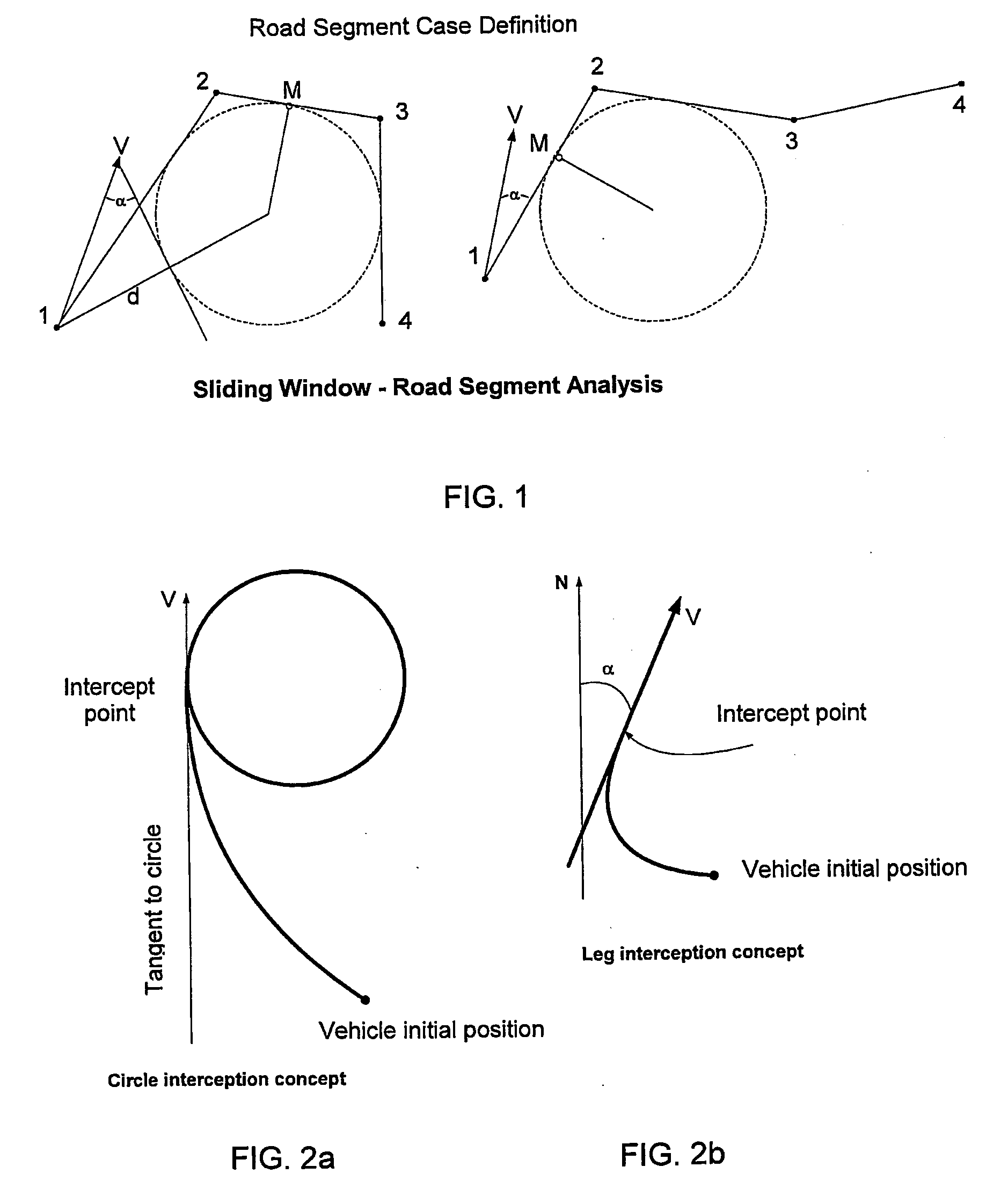
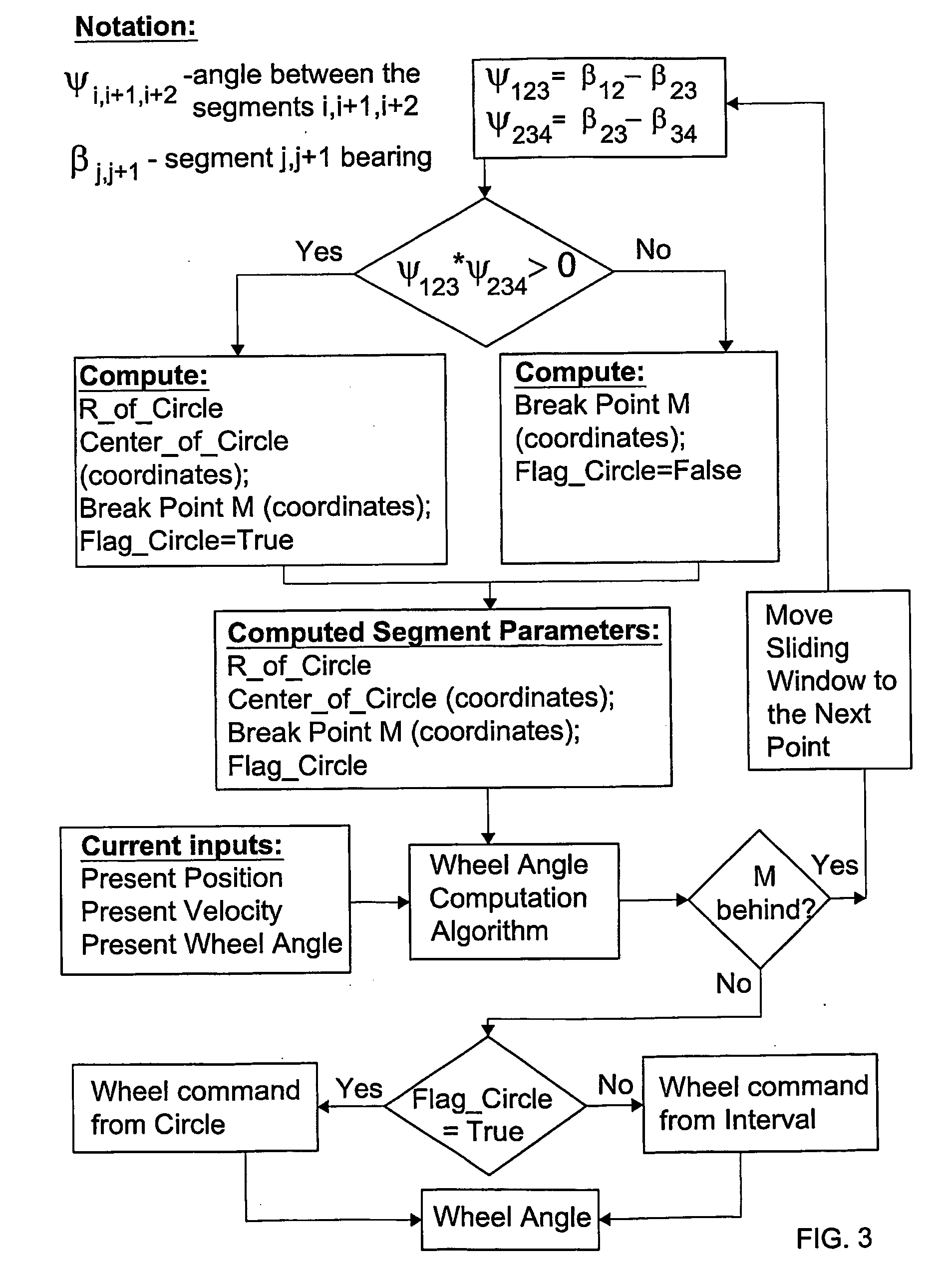
[0044]FIGS. 1a and 1b show schematically a pair of sliding windows 10, 11 each defining alternative path segments derived from four consecutive coordinates 1, 2, 3 and 4 of a vehicle trajectory. Also shown in both of the sliding windows 10, 11 is a point M that constitutes a breakpoint to which the vehicle is guided for so long as its current position is behind the breakpoint M. Once the current position is in front of the breakpoint M i.e. the vehicle has advanced past the breakpoint M, a new sliding window is selected and the breakpoint M is moved forward. Each sliding window defines three successive segments denoted by coordinate pairs (1, 2), (2, 3) and (3, 4). Denoting the respective bearings of these three segments by the notation β12, β23 and β34, the angle between the two segments (1, 2) and (2, 3) denoted by Ψ123 is given by:

Ψ123=β12−β23

[0045]Likewise, the angle between the two segments (2, 3) and (3, 4) denoted by Ψ234 is given by:

Ψ234=β23−β34

[0046]In accordance with the...


PUM


Abstract

An unmanned vehicle is guided by selecting locations along a predetermined mute defining adjacent first, second and third linear portions. If an imaginary circle can be constructed that is mutually tangential to all three linear portions or to projections thereof, the vehicle is guided according to the circle intercept method until it reaches an imaginary point of contact (M) between the circle and the second linear portion or passes its traverse. If an imaginary circle cannot be constructed that is mutually tangential to all three linear portions or to projections thereof, an imaginary circle is constructed that is mutually tangential to the first and second linear portions; and the vehicle is guided along according to the leg intercept method until it reaches an imaginary point of contact (M) between the circle and the first linear portion or passes its traverse. The process is repeated iteratively in respect of successive locations.

Description

FIELD OF THE INVENTION[0001]This invention relates to automatic guidance of unmanned vehicles.BACKGROUND OF THE INVENTION[0002]U.S. Pat. No. 6,453,238 (Brodie et al.) published Sep. 17, 2002 describes a navigation system for tracking the position of an object using a GPS receiver responsive to GPS signals for periodically providing updates to a navigation processor. The system also includes a dead reckoning sensor (beacon) responsive to movement of the object providing updates to a navigation processor. The navigation processor determines object navigation states and propagates the object navigation states between measurement updates using the movement measurements. The navigation system mimics the traditional Kalman filter by integrating separate GPS-navigation, heading and speed Kalman filters.[0003]U.S. Pat. No. 5,923,270 (Sampo et al.) published on Jul. 13, 1999 discloses an automatic steering system for unmanned vehicle that carries a navigation computer which receives position...

Claims


Application Information

Patent Timeline
Patent Type & Authority Applications(United States)
IPC IPC(8): G05D1/02G01S19/41G01C21/16
CPCG05D1/0223G05D1/0259G05D1/02G05D1/0272G05D1/0278G05D1/027
Inventor APPELMAN, DINAPINSKY, ALEXSIGAL, ARKADYTSENTSIPER, ARIEH
Owner ISRAEL AEROSPACE IND
Why Eureka
Try Eureka