Skate car

a technology for skate cars and skate wheels, applied in the field of skate cars, can solve the problems of monotonous movement, significantly more effort to drive the skate car, and inability to apply the force produced by both legs of the user,

Inactive Publication Date: 2010-08-12
HSIN LUNG ACCESSORIES CO LTD
View PDF1 Cites 10 Cited by
  • Summary
  • Abstract
  • Description
  • Claims
  • Application Information

AI Technical Summary

Benefits of technology

[0014]By swinging the handlebar to the left and right sides, the present invention can roll the front driving wheel along the S-shaped path to drive the car body forward, or apply a force alternately to swing the left and right support rods to the left and right sides to roll the left and right swayable and automatic position-restoring rear driving wheels forward along the S-shaped path to drive the car body, or do both, so as to drive the car body to move forward smoothly, achieve a multiple of operating modes and give more fun for the fitness exercise. Further, a through shaft of the front pipe is coupled to the left and right support rods through a vertical pivot and pivotally coupled to a pivotal ear of the front pipe through the transversal screw bolt, such that when the vertical pivot serves as a rotating point to lean both with each other or separate both from each other for the folding and unfolding operations respectively. The front pipe and the handlebar can use the through shaft as a rotating point for the folding and unfolding operations.

Problems solved by technology

1. Since a user can slide the whole car body forward by swinging the handlebar to left and right sides to swing the front driving wheel 13, but the force produced by both legs of the user cannot be applied alternately to the load carrying wheels 21 at the rear ends of the two support rods 20 to drive and move the car body, therefore it requires significantly more efforts to drive the skate car, and the movement is monotonous and even unsmooth and stiff.
2. Since the force produced by both legs of the user cannot be applied alternately to the two load carrying wheels 21, therefore a wheel may be lifted above the ground and give rise to an accident easily, when the car body is sliding and making a turn.
3. Since the second through shaft 141 is passed transversally through the elastic shock absorbing member 15 and accommodated in the shaft sleeve 203, therefore poor shock absorption and position restoration are resulted due to lateral forces when the handlebar 12 swings to left and right, and the operation of the skate car will be unnatural and stiff.
4. Since it is necessary to install a folding structure separately at a position proximate to the front end of the left and right support rods 20 before the skate car can be folded the folding structure not just requires more components only, but also incurs a troublesome, complicated, laborious and cost-ineffective manufacturing process.
5. After the left and right support rods 20 are spread open for use, the folding structure uses the pin 208 to the user's body weight solely, and thus there will be a risk of having deformations, separations, falling off or breaking of components of the skate car if forces are applied continuously to operate and drive the skate car to slide on various road surface while carrying the weight of the user.

Method used


Image

  • Skate car
  • Skate car
  • Skate car

Examples


Embodiment Construction

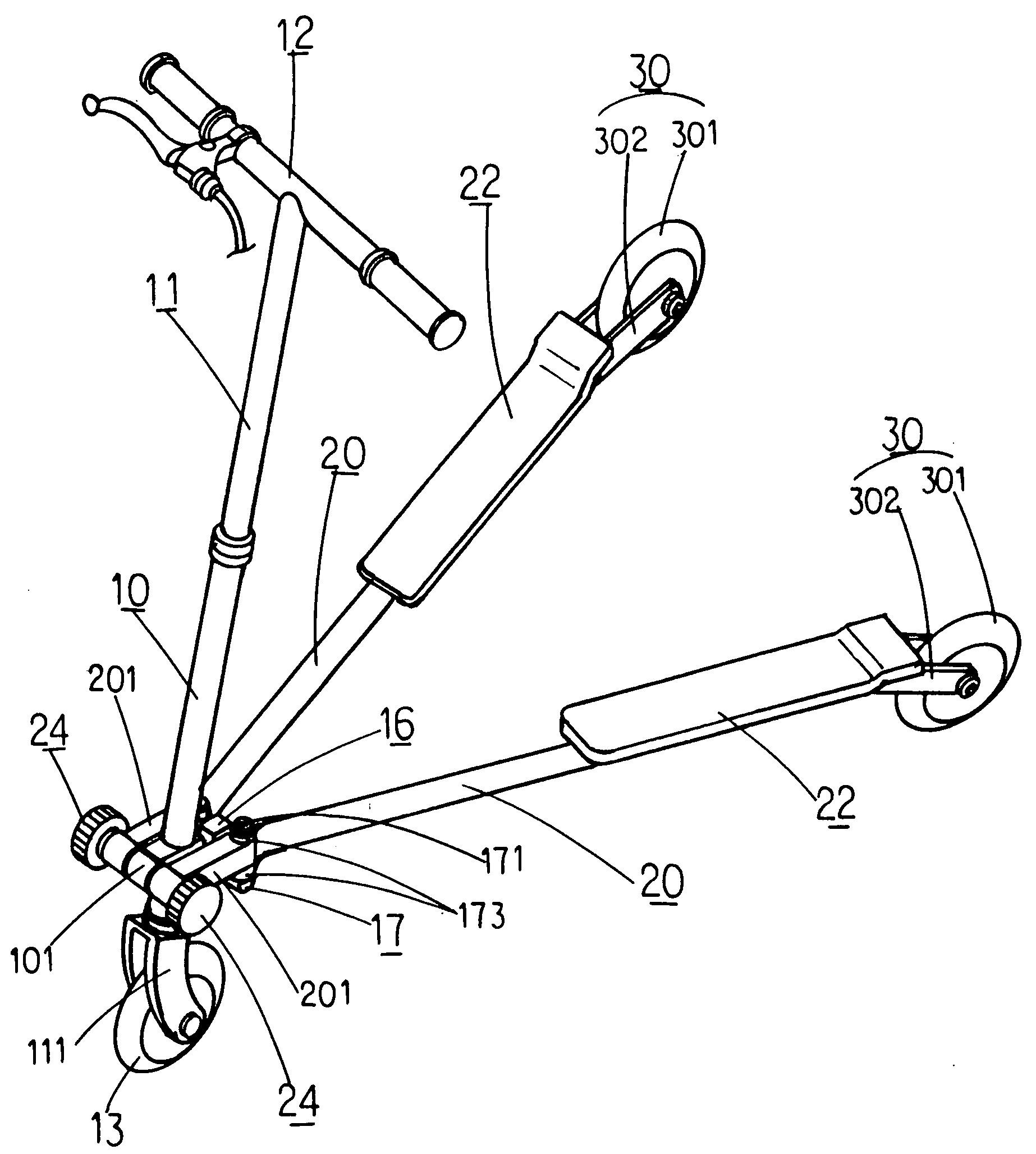
[0031]With reference to FIGS. 5 to 9 for an improved skate car of the present invention, the skate car comprises the skate car comprises a front pipe 10, a freely rotating vertical pipe 11 pivotally coupled to the front pipe 10, a handlebar 12 disposed at the top of the vertical pipe 11, a front driving wheel 13 installed at the bottom of the vertical pipe 11 through a front fork 111, a pivotal ear 101 disposed at the bottom of the front pipe 10, a pivotal base 106 disposed at a backward position corresponding to the pivotal ear 101, a swing block 6 is pivotally installed at the position of the pivotal base 106 by a pivot 161 and a cushion element 162 in corresponding front and back directions, and a through shaft 17 is transversally and pivotally coupled to a cushion element 170 at the position of the swing block 6, and both ends of the through shaft 17 are pivotally coupled to front ends of the left and right support rods 20 through a vertical pivot 171, a cushion element 172 and ...


PUM


Abstract

A skate car includes a left and right swayable front pipe coupled to front ends of the left and right support rods and an automatic position-restoring swayable driving wheel pivotally coupled to rear ends of left and right support rods separately. A user can either swing a vertical pipe of the front pipe to the left and right sides to swing the front driving wheel installed at the lower end of the vertical pipe, or apply a force to the left and right support rods to swing the swayable and automatic position-restoring left and right rear driving wheels to the left and right sides, or do both of the above, to drive the car body to roll forward along the S-shaped path and slide forward smoothly, so as to achieve a multiple of operating modes and gain more fun for the fitness exercise.

Description

BACKGROUND OF THE INVENTION[0001]1. Field of the Invention[0002]The present invention relates to an improved skate car capable of achieving a smooth sliding effect by a multiple of operations such as swinging a vertical pope to left and right sides, alternately applying a force to left and right support rods or swinging the vertical pope to left and right sides and alternately applying a force to the left and right support rods, and a vertical pipe with a front pipe working with left and right transversal screw bolts and left and right vertical pivots can be spread open or folded together directly with left and right support rods to spread open and fold the skate car easily and conveniently.[0003]2. Description of the Related Art[0004]In a triangular design of a skate car whose handlebar can be swayed to left and right sides to drive a car body as shown in FIGS. 1 and 2, the skate car comprises a front pipe 10, a freely rotating vertical pipe 11 pivotally coupled to the front pipe 1...

Claims


Application Information

Patent Timeline
Patent Type & Authority Applications(United States)
IPC IPC(8): B62M1/00B62K5/04
CPCA63C17/0033A63C17/012B62K3/002A63C2017/1472A63C17/12
Inventor FAN, JEENG-NENG
Owner HSIN LUNG ACCESSORIES CO LTD
Why Eureka
Try Eureka