Optical Operating Apparatus

Active Publication Date: 2009-11-19
PIXART IMAGING INC
View PDF2 Cites 5 Cited by
  • Summary
  • Abstract
  • Description
  • Claims
  • Application Information

AI Technical Summary

Benefits of technology

[0007]An optical operating apparatus having high reliability and multiple operating modes is provided.
[0016]The optical operating apparatus employs an optical manner to sense a change of the pressure, therefore, any operating error caused by electrostatic force or humidity can be prevented. The pressure is not exerted on the image sensing module, thereby avoiding a damage of the image sensing module. Therefore, the optical operating apparatus has high reliability. In addition, the optical operating apparatus has a function selecting module and therefore has multiple operating modes.

Problems solved by technology

Because the resistive operating apparatus has low sensitivity, in practical application, the resistive operating apparatus is prone to suffer too much pressure and tends to be damaged.
In addition, the capacitive operating apparatus has high price, and is easy to cause operating error because of electrostatic force or humidity.

Method used


Image

  • Optical Operating Apparatus
  • Optical Operating Apparatus
  • Optical Operating Apparatus

Examples


Embodiment Construction

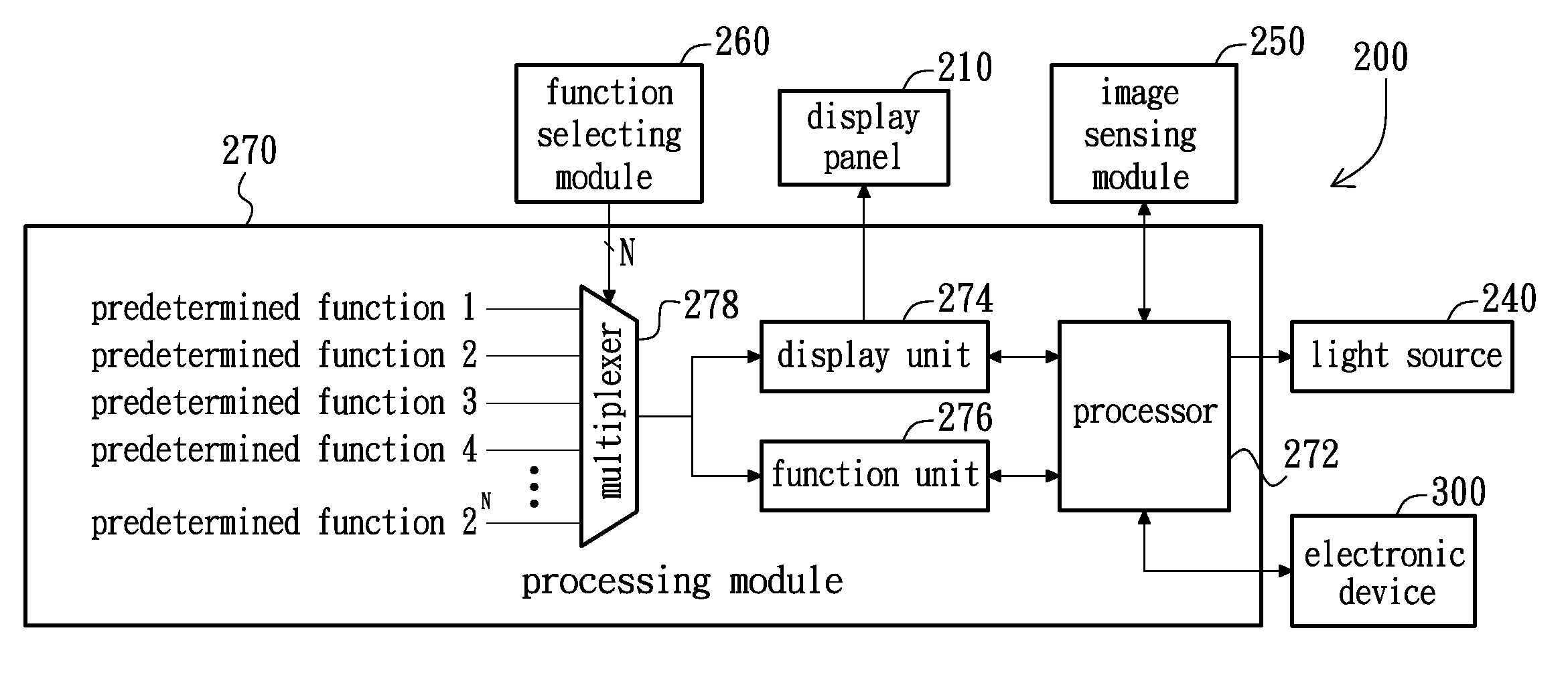
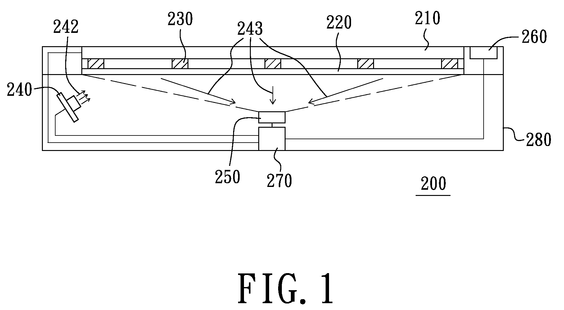
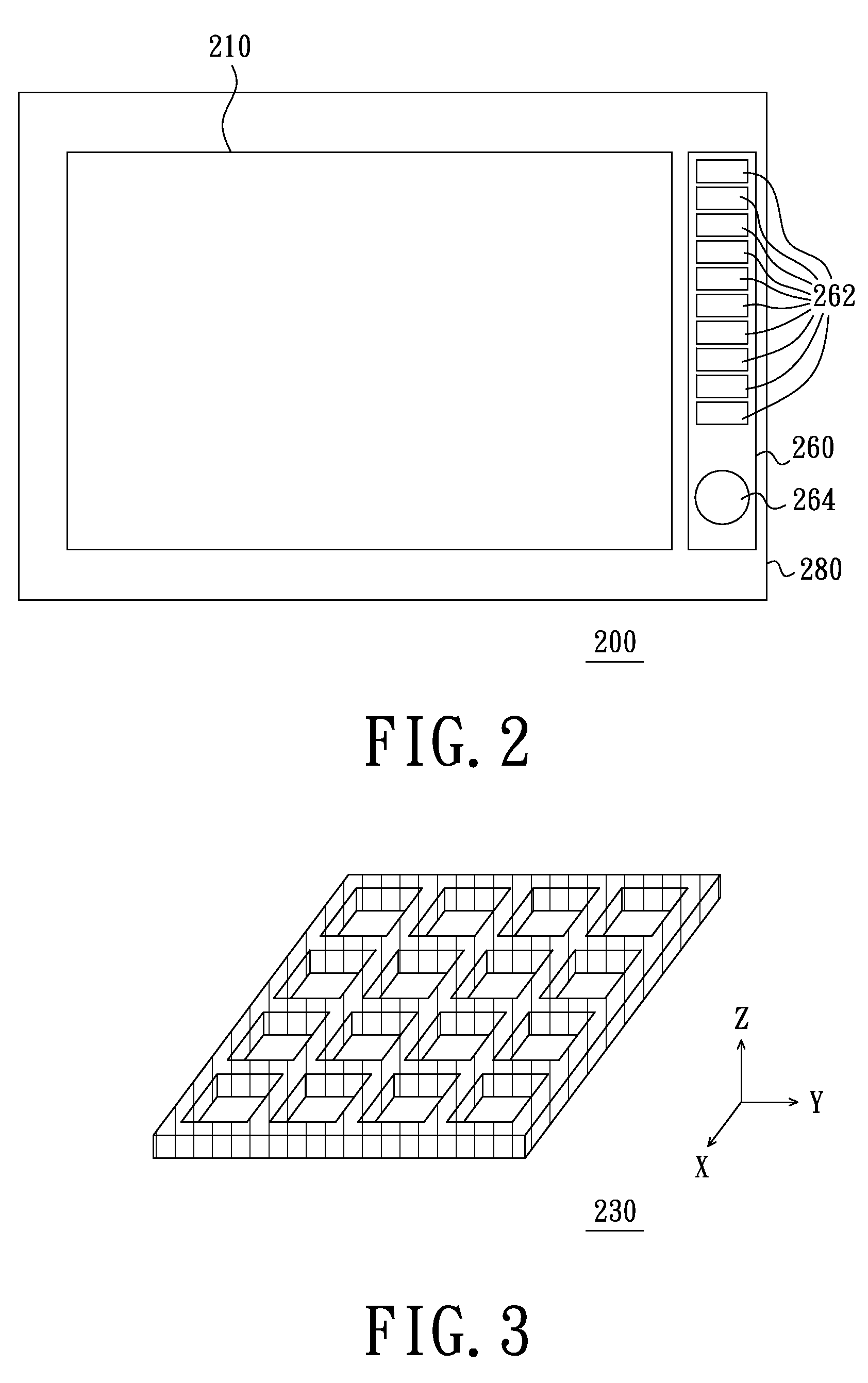
[0028]FIG. 1 is a schematic view of an optical operating apparatus of an embodiment of the present invention, FIG. 2 is a top view of the optical operating apparatus of FIG. 1 and FIG. 3 is a three-dimensional view of a deformable unit of the optical operating apparatus of FIG. 1. Referring to FIGS. 1 to 3, an optical operating apparatus 200 of the present embodiment can be connected to an electronic device, such as a computer, a television, a game player, and so on. The optical operating apparatus 200 includes a display panel 210, a transparent supporting plate 220, a deformable unit 230, a light source 240, at least one image sensing module 250, a function selecting module 260 and a processing module 270. The transparent supporting plate 220 is disposed under the display panel 210. The deformable unit 230 is arranged between the transparent supporting plate 220 and the display panel 210. The deformable unit 230 has a pattern configuration (e.g., a predetermined reticular configura...


PUM


Abstract

An optical operating apparatus includes a display panel, a transparent supporting plate, a deformable unit, a light source, an image sensing module, a function selecting module and a processing module. The deformable unit is disposed between the transparent supporting plate and the display panel. The deformable unit has a pattern configuration. The deformable unit deforms as applying an external force on the display panel and restores after the external force is removed. The light source provides a light beam to the deformable unit, and a visual field of the image sensing module covers the whole deformable unit. The function selecting module is disposed beside the display panel and has a plurality of function selecting buttons for selecting a predetermined function. The processing module is electrically connected with the display panel, the function selecting module, the image sensing module and the light source. The processing module is configured to control the display panel to display a predetermined picture according to a corresponding predetermined function.

Description

[0001]This application is a continuation-in-part application of U.S. patent application Ser. No. 12 / 119,641, filed on May 13, 2008.BACKGROUND[0002]1. Field of the Invention[0003]The present invention relates to an operating apparatus, particularly, to an optical operating apparatus.[0004]2. Description of Related Art[0005]With the development of flat panel display technology, more and more electronic products have a screen. In these electronic products, many products are operated by moving the cursors in the screens. Generally, two typical operating apparatuses, i.e., resistive operating apparatus and capacitive operating apparatus, are used to move the cursor in the screen. Because the resistive operating apparatus has low sensitivity, in practical application, the resistive operating apparatus is prone to suffer too much pressure and tends to be damaged. In addition, the capacitive operating apparatus has high price, and is easy to cause operating error because of electrostatic fo...

Claims


Application Information

Patent Timeline
IPC IPC(8): G06F3/042
CPCG06F3/0425G10H2220/096G10H1/34G10H1/0008
Inventor LIN, CHO-YIHSU, YAO-CHING
Owner PIXART IMAGING INC
Why Eureka
Try Eureka