System and method for determining a location area of a mobile user

Active Publication Date: 2009-06-18
INTERDIGITAL CE PATENT HLDG
View PDF2 Cites 56 Cited by
  • Summary
  • Abstract
  • Description
  • Claims
  • Application Information

AI Technical Summary

Benefits of technology

[0008]According to the present invention, the above-mentioned objects are particularly achieved in that, for determining a location area of a user using a mobile communication terminal in a geographical area covered by a mobile radio network, the geographical area is divided into a plurality of sub-areas. For example, the geographical area is divided into sub-areas of equal shape and size, having a diameter in the range of 50 to 150 meters. For example, the sub-areas are squares arranged in a grid, or hexagons arranged in a comb structure. Based on field strengths expected in the sub-areas for antennas located in the geographical area, and based on the antenna used by the mobile communication terminal, location probabilities are determined for the sub-areas. The location probabilities indicate the probability that the mobile communication terminal is located in the respective sub-area. Preferably, the location probabilities are determined based on antenna probabilities associated with the sub-areas. The antenna probabilities indicate for at least some of the antennas, the probability that the mobile communication terminal, when located in a particular sub-area, uses the respective antenna. The antenna probabilities are determined based on the field strengths expected in the s

Problems solved by technology

Unfortunately today calculations of these areas are not accurate, often they are too large or they are not reliable, and in reality mobile communication terminals are often located outside of these areas (low hit rate).
However, these values would have to be transmitted from the mobile telephones to a centralized measuring system and are therefore not necessarily available for locating a mobile telephone.
Furthermore, manufacturers of proprietary network components do not necessarily make such values available to the operators of mobile networ

Method used


Image

  • System and method for determining a location area of a mobile user
  • System and method for determining a location area of a mobile user
  • System and method for determining a location area of a mobile user

Examples


Example

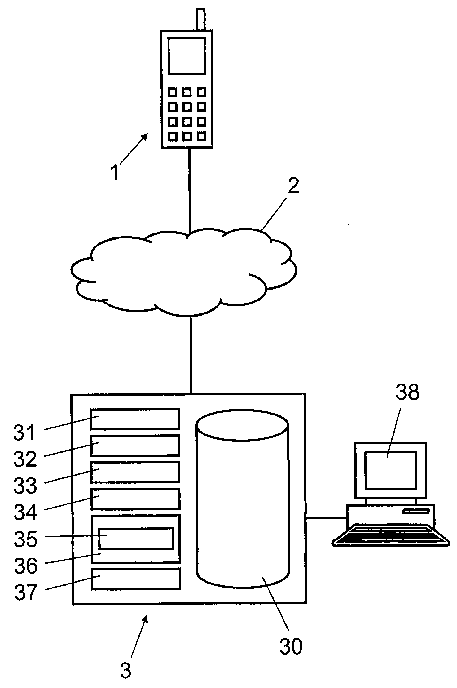
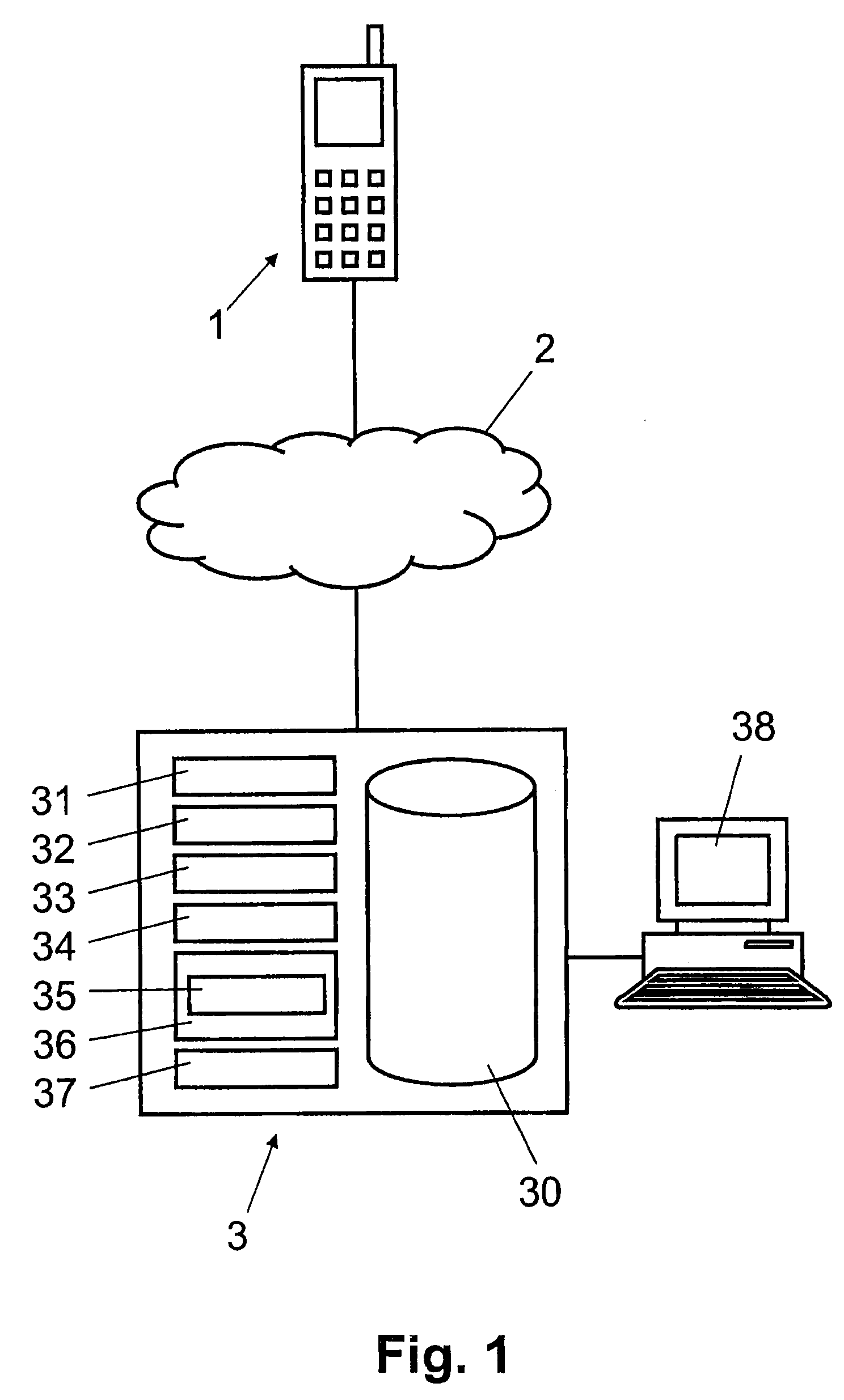
[0023]In FIG. 1, reference numeral 1 refers to a mobile communication terminal such as a mobile radio (cellular) telephone, a PDA or another portable computer. The mobile communication terminal 1 comprises a communication module for communicating (voice and / or data) via mobile radio network 2, e.g. a GSM or UMTS network or another cellular radio network. As illustrated schematically in FIG. 3, the cellular network comprises a plurality of antennas A1, A2, A3, A4, each covering a more or less overlapping area C1, C2, C3, C4 of the geographical area 4. Each antenna A1, A2, A3, A4 is controlled by a base station connected to a mobile switching center (e.g. MSC) of the mobile radio network 2. The antennas A1, A2, A3, A4 are identified by their identification id in the network, which correspond to the areas C1, C2, C3, C4.

[0024]In FIG. 1, reference numeral 3 refers to a computer system connected to the mobile radio network 2. Computer system 3 includes one or more computers, for example ...


PUM


Abstract

A computer system determines location probabilities for defined sub-areas (41, 43) of a geographical area (4), e.g. for squares arranged in a grid (40), based on field strengths expected in the small sub-areas (41, 43) from the antennas (A1, A2 A3, A4), and based on the antenna used by the mobile communication terminal. The location probabilities indicate for a sub-area (41, 43) the probability that the mobile communication terminal is located in the respective sub-area (41, 43). The computer system determines at least one ellipse defining the location area, based on the location probabilities of the sub-areas (41, 43). The location probabilities make it possible to determine elliptical location areas of mobile users much smaller than the area each antenna does cover physically, but without the need for measuring at the mobile communication terminal signal properties such as signal strength or observed time differences.

Description

FIELD OF THE INVENTION [0001]The present invention relates to a system and a method for determining a location area of a mobile user. Specifically, the present invention relates to a computer system and a computer-implemented method for determining a location area of a user using a mobile communication terminal in a geographical area covered by a mobile radio network.BACKGROUND OF THE INVENTION [0002]For various location based services as well as for handling emergency situations, it is essential to determine as accurately as possible the geographical location of a user of a mobile communication terminal. Mobile communication terminals include, for example, mobile radio (cellular) telephones or personal digital assistants (PDA) as well as other portable computers with communication modules for mobile radio networks, such as GSM (Global System for Mobile Communication) or UMTS (Universal Mobile Telecommunication System). Although there are mobile communication terminals available whi...

Claims


Application Information

Patent Timeline
IPC IPC(8): H04W4/02H04W4/021G01S5/02
CPCH04W64/003G01S5/0252H04W4/021G01S5/02521G01S5/0278H04B7/026
Inventor VERSTEEG, ERNSTTAILLARD, ERICBAILLY, PATRICKLAURENT, MAXENCE
Owner INTERDIGITAL CE PATENT HLDG
Why Eureka
Try Eureka