Magnetic resonance tomography device with localization system and method to localize a local coil

Active Publication Date: 2010-07-15
SIEMENS HEALTHCARE GMBH
View PDF12 Cites 24 Cited by
  • Summary
  • Abstract
  • Description
  • Claims
  • Application Information

AI Technical Summary

Benefits of technology

[0016]As already mentioned above, the electrical response of a magnetic field sensor is based on the effect of the magnetic field on the material or the respective material composition of the magnetic field sensor. Magnetically hard and soft materials or other solids such as semiconductors or resistance layers are typical. Assuming that the respective physical effect has an effect, magnetic field sensors can be categorized as follows: AMR sensors are based on the anisotropic magnetoresistive effect. Other magnetic field sensors use the effect known as “giant magnetoresistance” and are therefore designated as GMR sensors. The Wiegand effect is also used to realize magnetic field sensors designated as Wiegand sensors. Galvanometric effects in turn play a role in Hall sensors or field plates. Therefore the most varied realizations are considered as magnetic field sensors; attention should be paid to compatibility with the magnetic resonance tomography method. According to a preferred exemplary embodiment of the invention, however, one of the magnetic field sensors is formed with at least one Hall sensor that forms a magnetic field-sensitive sensor element of the magnetic field sensors. A single sensor element or multiple such sensor elements can be provided. GaAs transistors that change their properties (such as direct voltage response or RF response) under the effect of magnetic fields with relatively high field strength (see Proc. Intl. Soc. Mag. Reson. Med. 16 (2008) “Influence of magnetic filed on preamplifiers using GaAs FET technology”) are also suitable as possible alternatives (without being exhaustive, however).
[0017]In order to make sensor signals accessible to the central controller or an evaluation module, the transfer of sensor signals between the local coil and the central controller can ensue via already existing cables of the local coil with which the local coil can be connected to the MRT device. However, in order to avoid an additional expenditure in the already existing wiring, it has proven to be advantageous for the magnetic field sensors of the local coil to be fashioned f

Problems solved by technology

However, in operation it can occur that the local

Method used


Image

  • Magnetic resonance tomography device with localization system and method to localize a local coil
  • Magnetic resonance tomography device with localization system and method to localize a local coil
  • Magnetic resonance tomography device with localization system and method to localize a local coil

Examples


Example

DESCRIPTION OF THE PRIOR ART

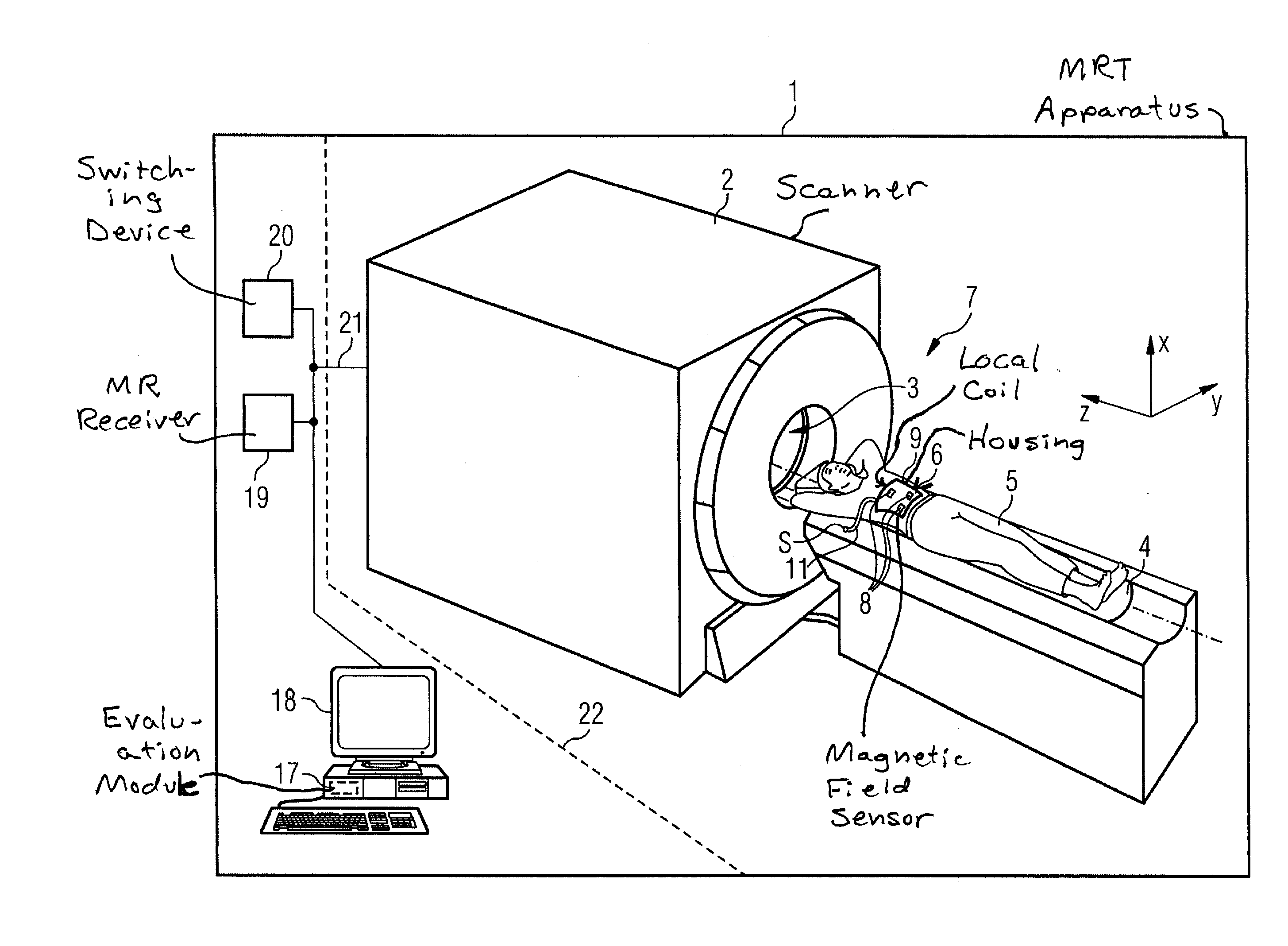
[0023]A magnetic resonance tomography apparatus 1 (that is abbreviated in the following as an MRT apparatus 1) is shown FIG. 1, wherein only those components which are necessary to describe the invention are shown in detail. For the purpose of orientation, the coordinate system of the MRT apparatus 1 is shown with the x-direction, y-direction and z-direction.

[0024]The MRT apparatus 1 has a scanner that accommodates the stationary magnet system (not explicitly shown) of the MRT device 1. The scanner 2 has a measurement space 3 that is also known as a “bore” in the technical jargon. A bed 4 on which a patient 5 is positioned can be inserted into this measurement space 3 in order to acquire raw data in this position for the reconstruction of volume image data. For this purpose a magnetic resonance signal is generated in the tissue of the body of the patient 5 with the use of the stationary magnet system. This magnetic resonance signal is received with the us...


PUM


Abstract

A magnetic resonance tomography device has a magnet system that generates a gradient field; with a local coil that receives a magnetic resonance signal; and with a localization system that is fashioned to locate the local coil. The localization system has a number of magnetic field sensors that are integrated with the local coil and fashioned to detect the gradient field. Such a device is used in a corresponding method for localization of a local coil in a magnetic resonance tomography device, and a local coil is fashioned so as to be suitable for this purpose.

Description

BACKGROUND OF THE INVENTION[0001]1. Field of the Invention[0002]The invention concerns a magnetic resonance tomography device of the type having a magnet system that is fashioned to generate a gradient field; with a local coil that is fashioned to receive a magnetic resonance signal; and with a localization system that is fashioned to localize the local coil. Moreover, the invention concerns a method to localize a local coil in such a magnetic resonance tomography device, as well as a local coil suitably fashioned for this purpose.[0003]2. Description of the Prior Art[0004]Magnetic resonance tomography (also called MRT) is a technique in widespread use for the acquisition of images of the inside of the body of a living examination subject. In order to obtain an image with this method, i.e. to generate a magnetic resonance exposure of an examination subject, the body or the body part of the patient that is to be examined must be exposed to an optimally homogeneous, static basic magne...

Claims


Application Information

Patent Timeline
IPC IPC(8): G01R33/48
CPCG01R33/3692G01R33/341
Inventor BIBER, STEPHANHEUBES, PETERSCHNELL, WILFRIED
Owner SIEMENS HEALTHCARE GMBH
Why Eureka
Try Eureka