
Arrangement and method for detecting an object which is arranged on a body, in particular for carrying out a security check

Inactive Publication Date: 2010-11-18
LUDWIG MAXIMILIANS UNIV MUNCHEN
View PDF4 Cites 4 Cited by
  • Summary
  • Abstract
  • Description
  • Claims
  • Application Information

AI Technical Summary

Benefits of technology

[0016]In contrast to radar methods, the transit time of an electromagnetic signal, in the present case of the detection radiation, from the emission device via the object or the body to the receiver device is not measured. Because on the one hand, information provided by transit time measurements of this type, namely the distance of the object from the detection arrangement, is not required, since it is a matter only of detecting the presence of the object to be detected. And on the other hand, the volume of data associated with this information would considerably increase the expenditure in terms of equipment. It should further be taken into consideration that a travel distance difference of 1 mm requires a resolution per time unit of the transit time signal of approx. 3 ps, which would require a correspondingly fast and thus cost-intensive electronic system. In comparison thereto the evaluation of vibration phase differences is considerably more cost-effective.

Problems solved by technology

However, this method fails, for example, with ceramic knives.
All of these methods have the disadvantage in common that they relate only to specific classes of substances.
In particular for reasons of time, however, the successive use of several technologies of this type in security checks is not practicable.
However, this method cannot be applied to the human body or only to a very limited extent.

Method used


Image

  • Arrangement and method for detecting an object which is arranged on a body, in particular for carrying out a security check
  • Arrangement and method for detecting an object which is arranged on a body, in particular for carrying out a security check
  • Arrangement and method for detecting an object which is arranged on a body, in particular for carrying out a security check

Examples


Embodiment Construction

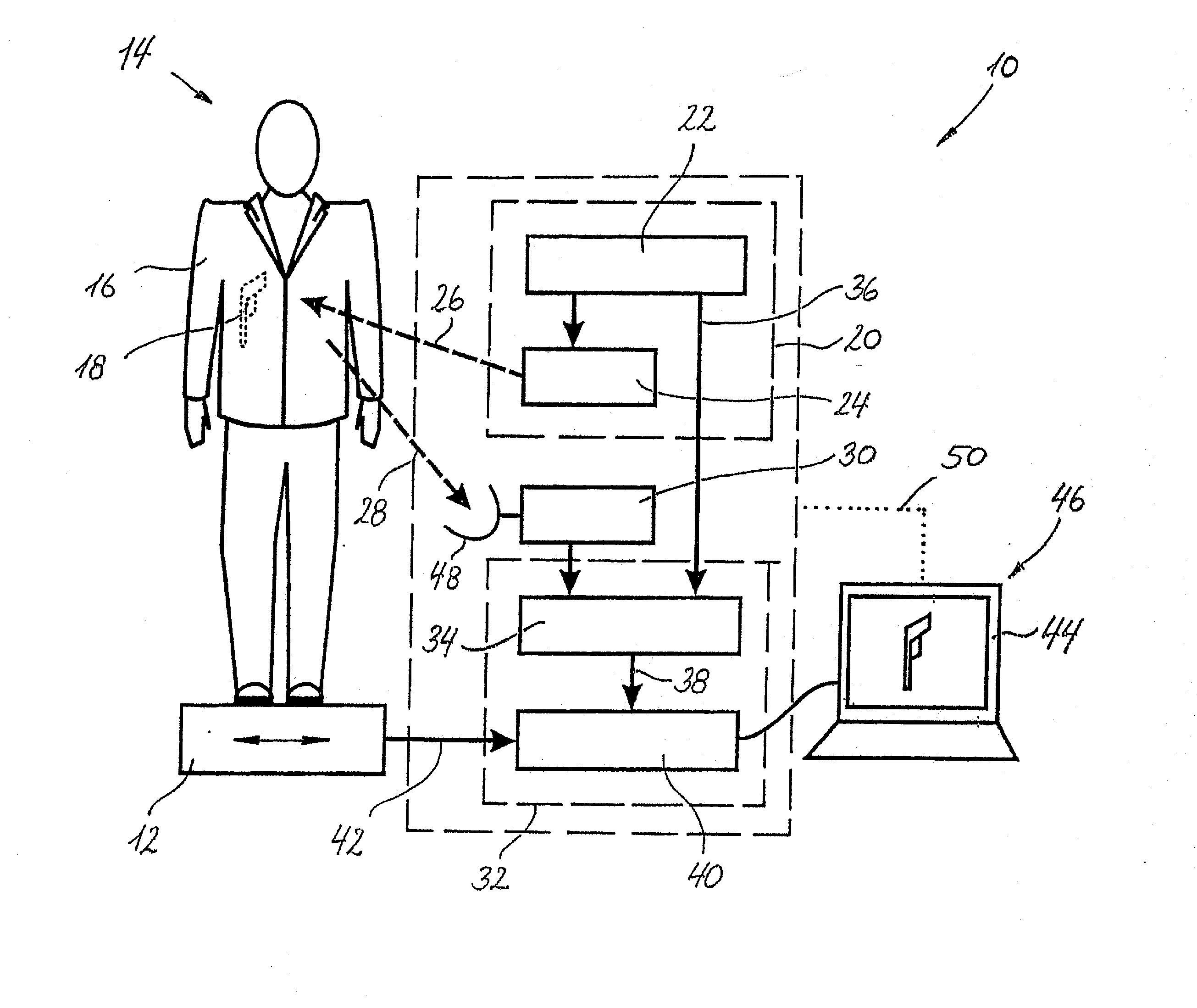
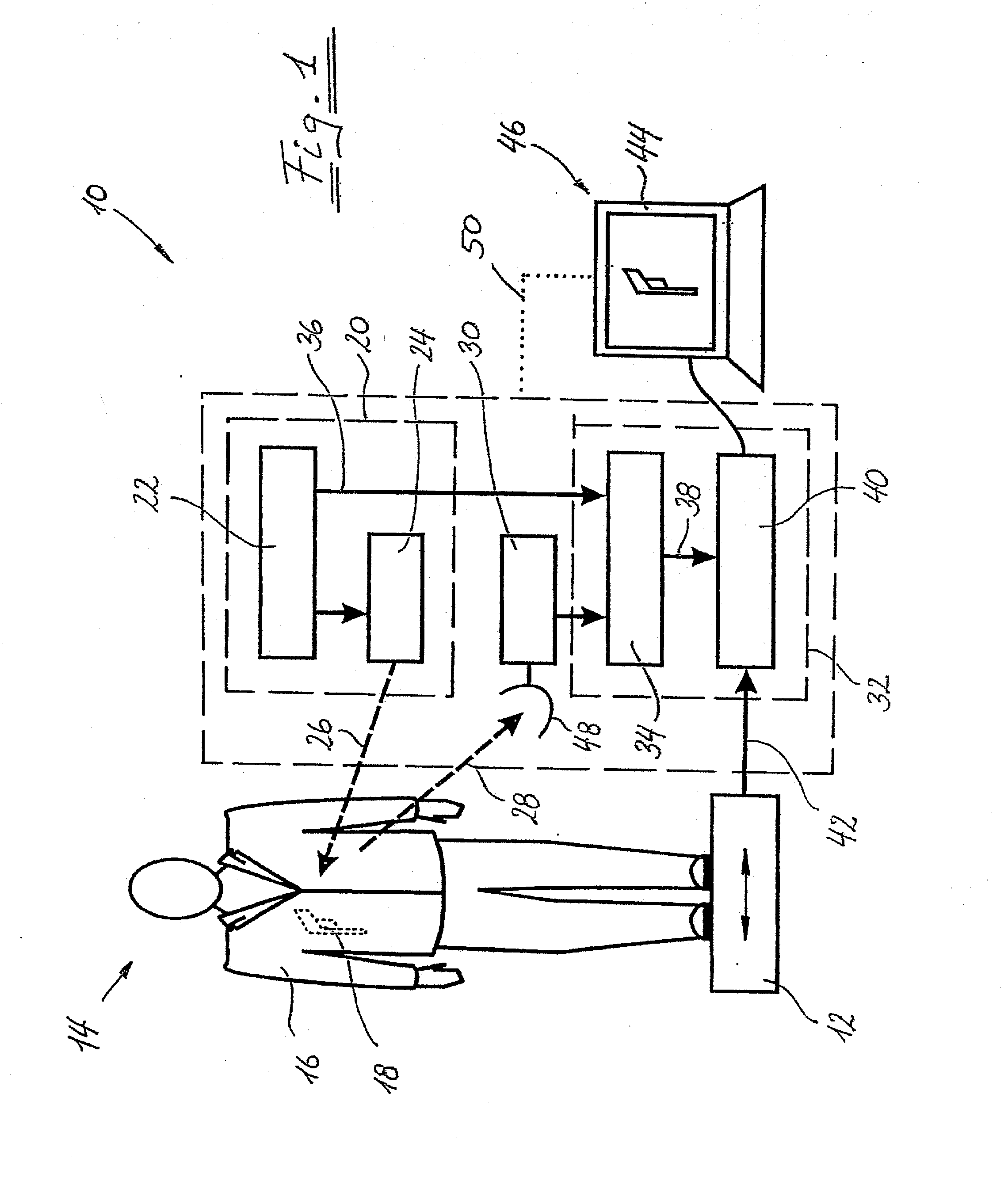
[0033]FIG. 1 shows a detection arrangement according to the invention labeled generally by 10. It comprises a vibration plate 12, on which the body to be examined, in the present case the person 14 to be examined, is arranged. The person 14 carries concealed beneath his clothing 16 an object 18, in the present case a handgun, and it is the object of the detection arrangement 10 to detect this object 18.

[0034]To this end, the vibration plate 12 is set in vibration with a predetermined frequency and a known phase, wherein this vibration as a forced vibration is also transferred to the body of the person 14 together with his clothing 16 and the handgun 18 carried in a concealed manner. The resulting movement of the person 14, the clothing 16 and the concealed object 18 is scanned by means of terahertz radiation.

[0035]To this end, the detection arrangement 10 comprises an emission device 20 with a radiation generation device 22 for terahertz radiation, which can contain, for example, a ...


PUM


Abstract

The invention relates to an arrangement (10) and a method for detecting an object (18) arranged on a body (14). The arrangement comprises a vibration device (12), which sets the body (14) in a mechanical vibration of predetermined vibration frequency and predetermined vibration phase, an emission device (20) which emits in the direction of the body (14) a coherent electromagnetic detection radiation (26), the radiation frequency of which is selected such that it is reflected at least in part by the body (14) and the object (18) to be detected, a receiver device (30), which receives the radiation (28) reflected by the body (14) and the object (18), and an evaluation device (32) which filters out of the radiation (28) received the portions having the predetermined vibration frequency and evaluates them with respect to their vibration phase difference from the predetermined vibration phase.

Description

CROSS-REFERENCE TO RELATED APPLICATIONS[0001]The present application is a U.S. National Stage of International Patent Application No. PCT / EP2007 / 009000 filed Oct. 17, 2007 and claims priority under 35 U.S.C. §119 of German Patent Application No. 10 2006 049 152.1 filed Oct. 18, 2006. Moreover, the disclosure of International Patent Application No. PCT / EP2007 / 009000 is expressly incorporated by reference herein in its entirety.BACKGROUND OF THE INVENTION[0002]1. Field of the Invention[0003]The invention relates to an arrangement and a method for detecting an object arranged on a body, but possibly concealed by at least one covering material.[0004]2. Discussion of Background Information[0005]Arrangements of this type are generally known. For example, at airports or at large events metal detectors are used for security control, with the aid of which metal weapons can be detected. However, this method fails, for example, with ceramic knives. Furthermore, it is known that with the aid of...

Claims


Application Information

Patent Timeline
IPC IPC(8): G01N21/84G01N21/17
CPCG01N21/3563G01N21/3581
Inventor KERSTING, ROLAND
Owner LUDWIG MAXIMILIANS UNIV MUNCHEN
Learn More