Retaining Device for Thin, Planar Substrates

a thin, planar substrate technology, applied in the direction of conveyors, conveyor parts, transportation and packaging, etc., can solve the problems of increasing the expenditure of mechanical equipment, clamming together the substrate in the form of a chain on the one hand, and rigid formation of the retaining clips

Active Publication Date: 2012-09-27
GEBR SCHMID GMBH & CO
View PDF10 Cites 5 Cited by
  • Summary
  • Abstract
  • Description
  • Claims
  • Application Information

AI Technical Summary

Problems solved by technology

However, the clamping together of the substrates in the form of a chain on the one hand and the rigid formation of the retaining clips on the other hand are problematic here.
Excessive height adjustability is accompanied by greatly increasing expenditure for the mechanical equipment.
Alternatively, they may also transversely span the path running through, which however is considered to be less advantageous.

Method used


Image

  • Retaining Device for Thin, Planar Substrates
  • Retaining Device for Thin, Planar Substrates
  • Retaining Device for Thin, Planar Substrates

Examples


Embodiment Construction

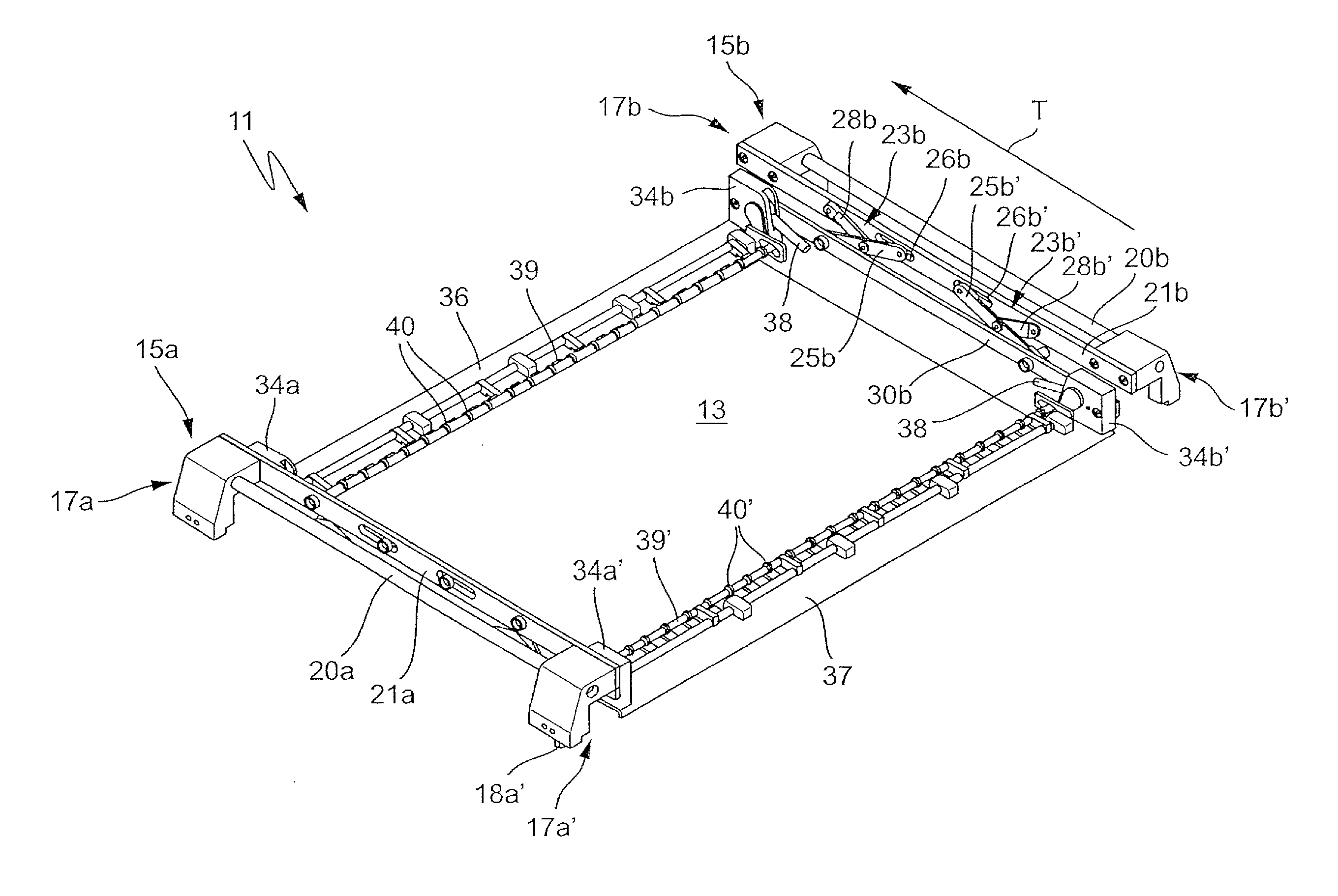
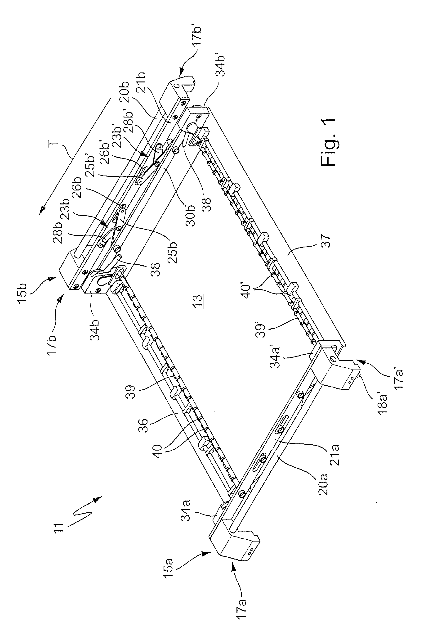
[0025]FIG. 1 illustrates in an oblique plan view a retaining device 11 according to the invention in which a printed circuit board 13 is held or restrained. The retaining device 11 has a left-hand transporting carriage 15a and a right-hand transporting carriage 15b, which may be formed identically or as mirror images of each other. A transporting carriage 15 respectively comprises a front transporting part 17a and a rear transporting part 17a′ or 17b and 17b′. The transporting parts 17 may, as illustrated, have downwardly pointing transporting projections 18a′, with which they are hung on circulating transporting chains or the like in a way similar to the document cited at the beginning DE 10 2007 038 116 A1. Alternatively, the transporting parts 17 may have rollers for transporting on a rail or the like, the retaining devices 11 then being driven in a way not shown.

[0026]The two transporting parts 17a and 17a′ or 17b and 17b′ are respectively connected to each other by means of con...


PUM


Abstract

A retaining device for printed circuit boards is of a frame-like form, with transporting carriages arranged on the outer longitudinal sides and intended for transporting the retaining device, a retaining frame of the retaining device for the substrates being arranged between the transporting carriages. The retaining frame is mounted height-adjustably on the transporting carriages and so a substrate restrained in it can be lowered or raised during the treatment.

Description

CROSS-REFERENCE TO RELATED APPLICATIONS[0001]This application is a continuation of PCT Application No. PCT / EP2010 / 064318, filed Sep. 28, 2010, and claims priority to DE 10 2009 049 905.9 filed Oct. 12, 2009, the disclosures of which are hereby incorporated by reference in their entirety.FIELD OF APPLICATION AND PRIOR ART[0002]The invention relates to a retaining device for thin sheet-like or planar substrates, for example thin printed circuit boards or so-called conductor foils or solar cells, the substrates being advantageously transported with the retaining device through treatment installations or continuously operating installations.[0003]It is known for example from US 2010-0126829 A1 to fasten substrates such as thin printed circuit boards by their front edge or their rear edge to an elongated clip. These elongated clips are then fixed or hung with their ends on transporting chains running to the left and right alongside a continuously operating installation and are transporte...

Claims


Application Information

Patent Timeline
Patent Type & Authority Applications(United States)
IPC IPC(8): B65G35/06
CPCH01L21/67721H01L21/67706H05K2203/0165B65G49/05B65G49/061B65G2201/022
Inventor LINK, BERNDDETTLING, TOBIAS
Owner GEBR SCHMID GMBH & CO
Why Eureka
Try Eureka