Suspension system for sliding doors

a suspension system and sliding door technology, applied in door/window fittings, multi-purpose tools, construction, etc., can solve the problems of no, or only very simple, inexpensive measures required to prevent the movable panel from tilting in the suspended condition, and achieve the effect of saving manufacturing costs and simple structur

Inactive Publication Date: 2011-02-24
DORMA GMBH & CO KG
View PDF2 Cites 6 Cited by
  • Summary
  • Abstract
  • Description
  • Claims
  • Application Information

AI Technical Summary

Benefits of technology

Thus, in such a suspension system there is only one running rail. The rollers, seen in a travel direction of the movable panel, are disposed at a side of the respective carriage. Thus, the rollers disposed at the opposite side of the carriage, as well as the associated running rail are eliminated, which results in cost savings and in reducing the friction resistance caused by the rollers. Furthermore, such a suspension system offers the advantage of a simple installation. Instead of introducing the carriages from a front side into the guiding rails and to attach them at the movable panel in a cumbersome manner, it is now possible to attach the carriages at the movable panel prior to placing them on the one running rail. Once the carriages are mounted, the at least one movable panel can be suspended from the front, i.e. seen in a direction transversely to the travel direction of the movable panel.
This leg of the U-shaped profile preferably has a projection, which extends from a free end of this leg towards the movable panel. In this case, while preferably passing through a through-opening configured in the projection, the screw is screwed into a contact member. The contact member has an oblique surface at a side facing the movable panel. This oblique extending surface is slanted in the direction of the head of the screw such that the contact member tapers towards the head of the screw. At a side facing the contact member, the clamping jaw has an oblique surface configured complementary to the oblique surface of the contact member. It is with this oblique surface that the contact member comes to lie at the clamping jaw. The oblique surfaces increase the expenditure of forces which is necessary to release the clamping jaw from the movable panel. This enhances the safety, when clamping the movable panel.

Problems solved by technology

It is thereby possible that the movable panel does not generate any torque in the area of the rollers, which could cause the movable panel to tilt in the suspended condition.
Therefore, there are no, or only very simple, inexpensive measures required to prevent the movable panel from tilting.

Method used


Image

  • Suspension system for sliding doors
  • Suspension system for sliding doors
  • Suspension system for sliding doors

Examples


sixth embodiment

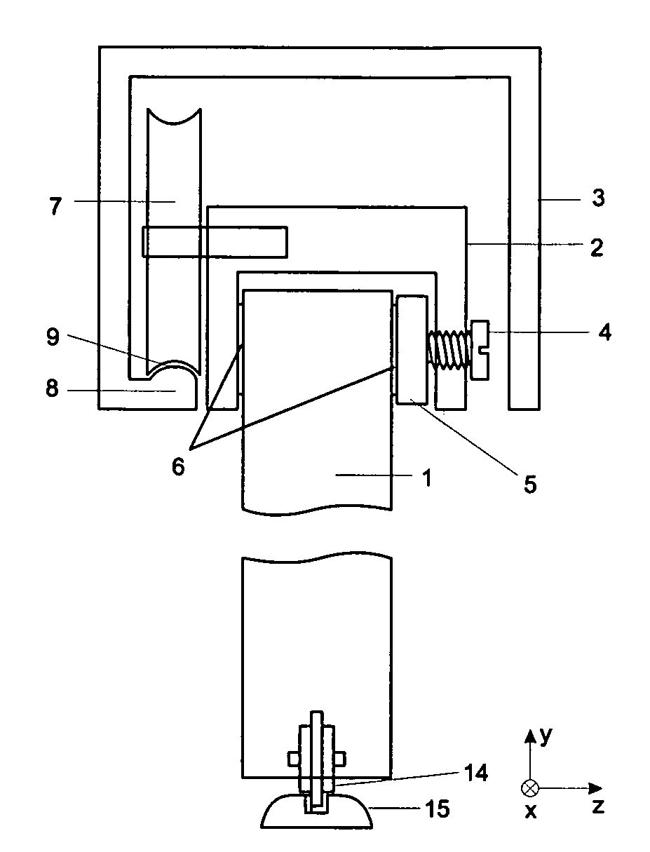
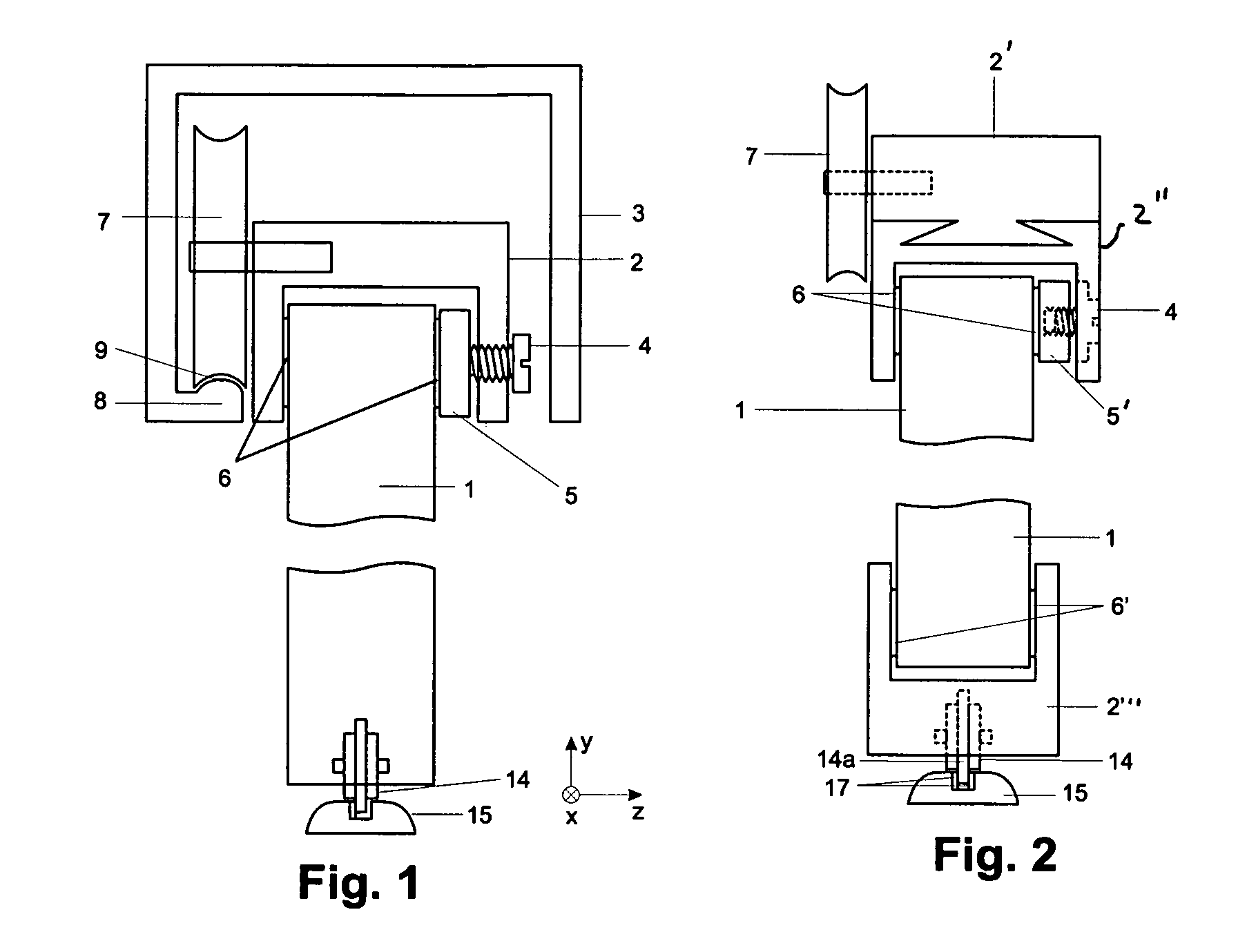
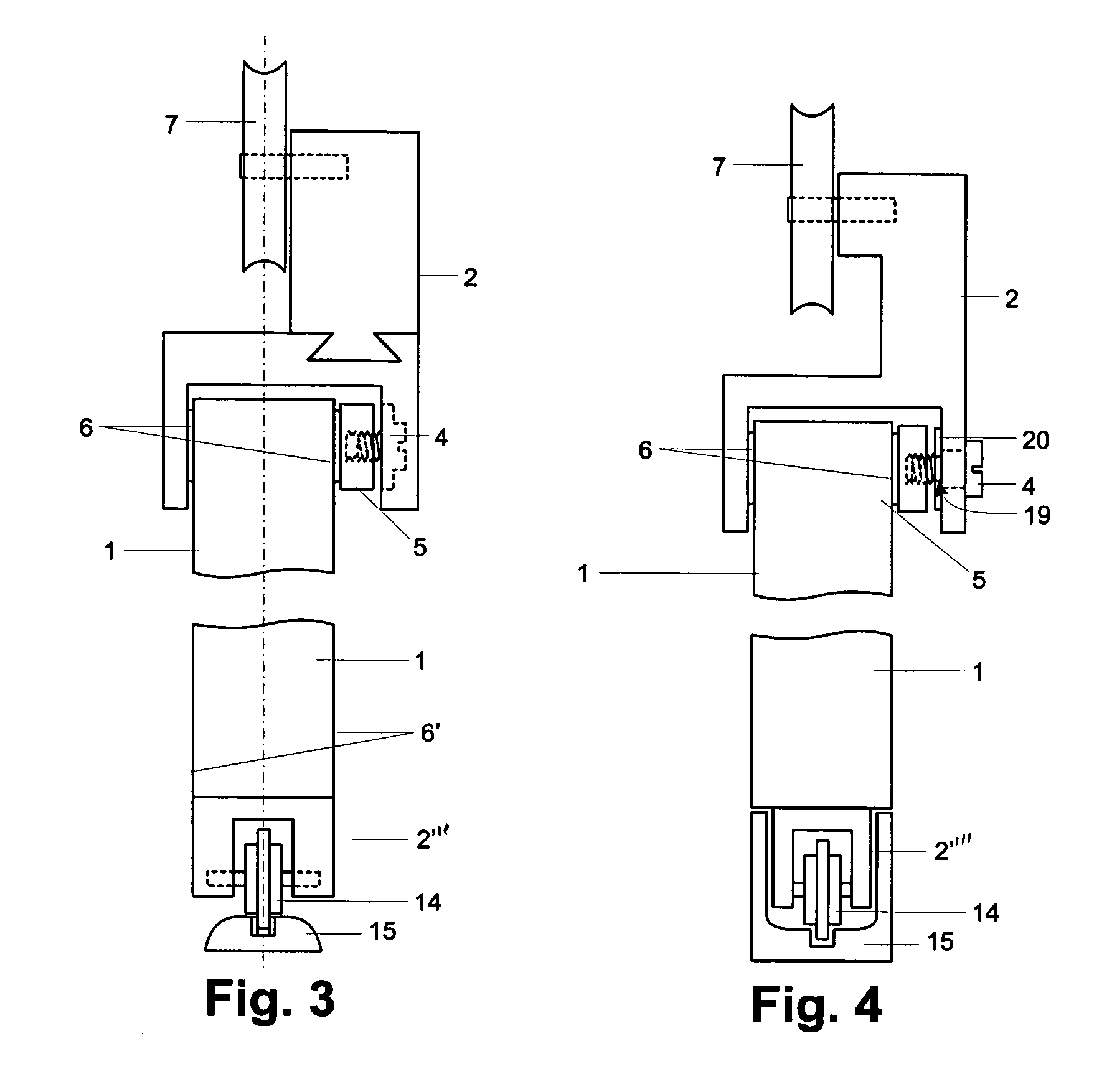
A suspension system according to the invention is illustrated in FIG. 6.

The leg of the carriage 2, on the side of which the clamping jaw 5 is disposed, has a projection 22 at its free end. The projection 22 protrudes from said leg essentially vertically in the direction of the sliding door leaf 1. The projection 22 has a through-opening, which is configured to extend in vertical direction in FIG. 6. The screw 4 passes through the through-opening of the projection 22 from an outer side of the projection 22 and is screwed into a female thread configured in a contact member 21. A surface of the head of the screw 4 facing the projection 22 is preferably supported at the projection 22 itself.

The contact member 21 has an oblique surface at a side facing the clamping jaw 5. This oblique extending surface is configured slanted in the direction of the head of the screw 4 such that the contact member 21 tapers towards the head. At a side facing the contact member 21, the clamping jaw 5 has an...


PUM


Abstract

A suspension system for at least one panel movable along a travel path is disclosed. The suspension system has at least two carriages for the at least one movable panel. The at least two carriages are stationarily mounted at an upper section of the at least one movable panel and are disposed to extend essentially in a direction transversely to the travel path and parallel to a vertical extension of the at least one movable panel. Rollers are freely rotatably disposed at each carriage. The rollers are disposed to roll on a running surface of a running rail of the suspension.

Description

BACKGROUND OF THE INVENTION1. Field of the InventionThe invention relates to a suspension system for sliding doors, in particular for all-glass sliding door leaves.2. Related ArtSuspension systems for sliding doors based on rollers and / or on a magnetic carrying device are known.In suspension systems for sliding doors based exclusively on rollers, a respective sliding door leaf is usually suspended from two carriages. Seen horizontally in a travel direction of the sliding door leaf, rollers are freely rotatably disposed at the sides. At least two rollers, disposed at opposite sides of one carriage, roll in this case on running surfaces of running rails, wherein the running surfaces point in one and the same vertical direction. This means, two rollers roll respectively on a lower or respectively on an upper running rail.One disadvantage results from an unfavourable mounting of such a sliding door leaf. The carriages need to be introduced, respectively into the running rails from a fro...

Claims


Application Information

Patent Timeline
Patent Type & Authority Applications(United States)
IPC IPC(8): E05D15/16E05F15/56
CPCE05D15/063E05D15/0656E05Y2600/502Y10T16/361E05Y2900/132E05F15/632Y10T16/364E05Y2800/672E05F15/641
Inventor BUSCH, SVEN
Owner DORMA GMBH & CO KG
Why Eureka
Try Eureka