Image processing system, image processing device, non-transitory computer readable recording medium and processing device

Active Publication Date: 2016-01-07
KONICA MINOLTA INC
View PDF8 Cites 10 Cited by
  • Summary
  • Abstract
  • Description
  • Claims
  • Application Information

AI Technical Summary

Benefits of technology

[0018]According to an aspect of the non-transitory computer readable recording medium, execution of the program by the processing device causing the processing device to execute the steps of: receiving load statuses at the multiple image processing devices; determining one of the multiple image processing devices that communicates with the portable terminal based on the received load statuses at the multiple image processing devices; determining target

Problems solved by technology

If the job is sent to such image processing device to which the portable terminal is automatically connected, it takes long time for the job to be executed, resulting in ineffici

Method used


Image

  • Image processing system, image processing device, non-transitory computer readable recording medium and processing device
  • Image processing system, image processing device, non-transitory computer readable recording medium and processing device
  • Image processing system, image processing device, non-transitory computer readable recording medium and processing device

Examples


Example

First Embodiment

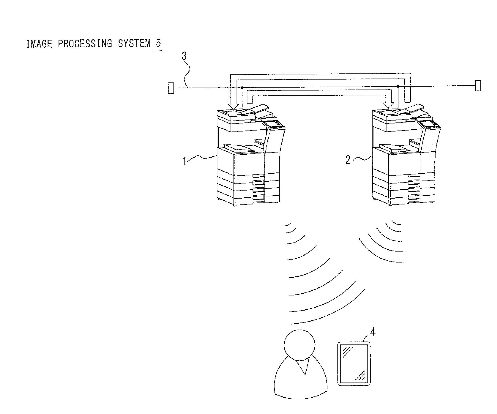
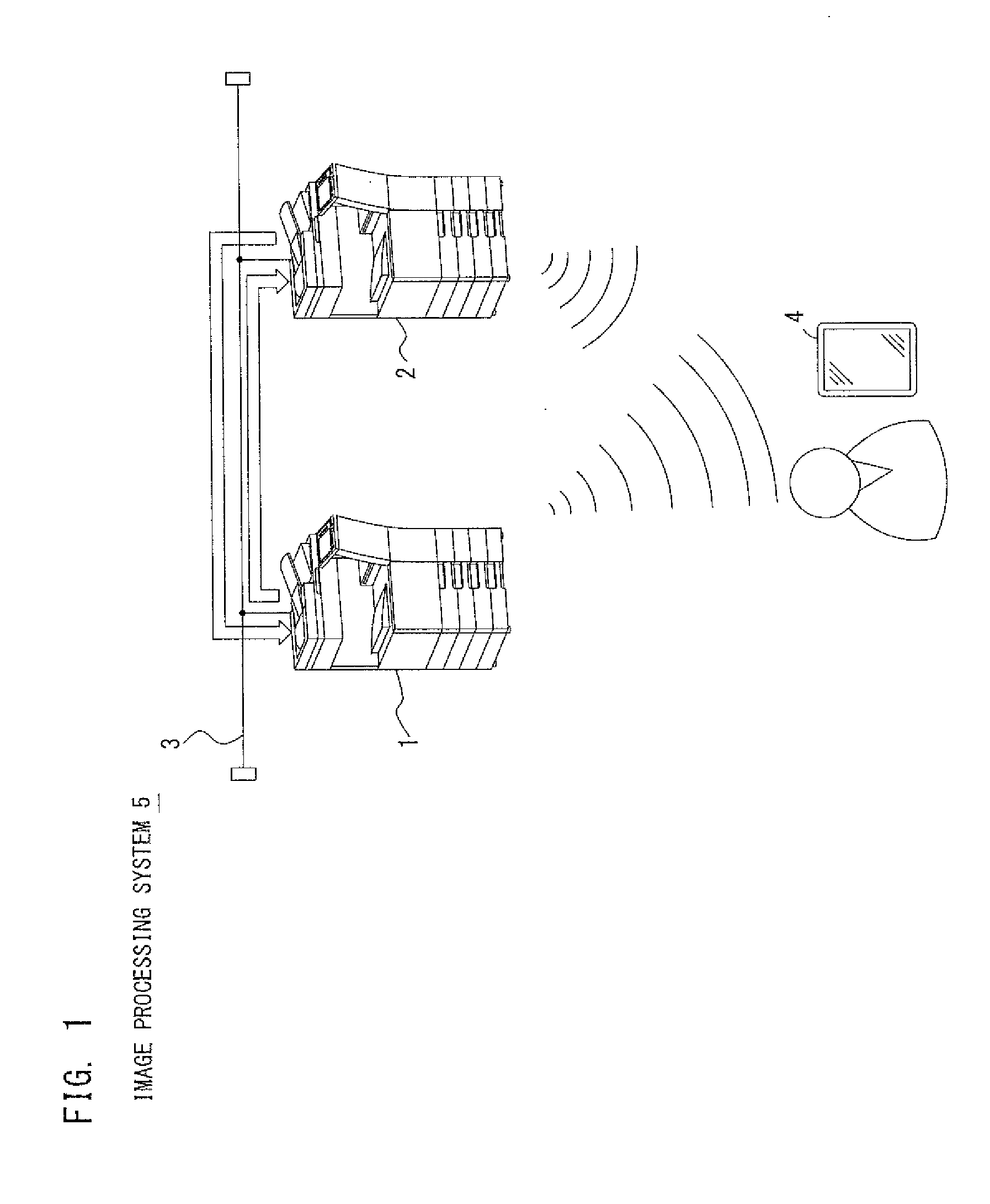
[0035]FIG. 1 shows an example of the structure of an image processing system 5. The image processing system 5 includes a first image processing device 1, a second image processing device 2 and a network 3 formed from a LAN which allows communication of the first image processing device 1 and the second image processing device 2. Each of the first image processing device 1 and the second image processing device 2 is, for example, constructed by one of MFPs (Multi-functional Peripherals) equipped with an image processing function such as a print function and / or a scan function. The first image processing device 1 and the second image processing device 2 are capable of executing jobs received over the network 3. Each of the first image processing device 1 and the second image processing device 2 is equipped with a wireless communication function using radio waves from Bluetooth (trademark) or WiFi, for example. The first image processing device 1 and the second image pr...

Example

Second Embodiment

[0077]A second embodiment is described next. In the aforementioned description of the first embodiment, the first image processing device 1 determines it establishes new communication with the portable terminal 4 when the load status at the second image processing device 2 does not meet any of the predetermined conditions in the status analysis (step S5 of FIG. 5) to analyze the load status information of the second image processing device 2. According to the second embodiment, the load statuses at the respective devices, the first image processing device 1 and the second image processing device 2, are compared. Determination to determine which device has less workload is made based on a predetermined priority condition, and either the first image processing device 1 or the second image processing device 2 thereby determined establishes new communication with the portable terminal 4.

[0078]FIG. 9 is a flowchart showing an example of the procedure performed at the fir...

Example

Third Embodiment

[0085]A third embodiment when there are multiple second image processing devices 2 is described next. The image processing system 5 of the third embodiment includes multiple second image processing devices 2. The communication determining part 23 of the first image processing device 1 compares the load status at each of the second image processing devices 2, and determines one of the image processing devices to which the least load is applied establishes new communication with the portable terminal 4. The radio adjuster 24 relatively increases the radio field strength from the image processing device thereby determined higher than the radio field strengths from the other second image processing devices. The radio field strength from the image processing device to which the least load is applied of the multiple second image processing devices 2 becomes relatively high. For executing the new job, the portable terminal 4 automatically connects to the image processing de...


PUM


Abstract

An image processing system includes a first image processing device including a first processor. The first processor executes a process including: detecting a change in a load status at the first image processing device; sending a request for information relating to a load status at the second image processing device to the second image processing device when the change in the load status at the first image processing device is detected; analyzing the information relating to the load status at the second image processing device, and determining whether or not the first image processing device establishes wireless communication with a portable terminal; and adjusting to relatively lower a radio field strength from the first image processing device below the radio field strength from the second image processing device when the first image processing device determines not to establish wireless communication with the portable terminal.

Description

[0001]This application is based on Japanese Patent Application No. 2014-136676 filed in Japan on Jul. 2, 2014, the contents of which are hereby incorporated by reference.BACKGROUND[0002]1. Field of the Invention[0003]One or more embodiments of the present invention relate to an image processing system, an image processing device, a non-transitory computer readable recording medium and a processing device. More specifically, one or more embodiments of the present invention relate to a technique of establishing wireless communication via radio waves with a portable terminal.[0004]2. Description of the Background Art[0005]Image processing devices including MFPs (Multi-Functional Peripherals) equipped with functions such as print function and scan function are generally used with network access, and capable of receiving jobs such as a print job over the network. The image processing device establishes wireless communication with a portable terminal such as a tablet terminal or a smart p...

Claims


Application Information

Patent Timeline
IPC IPC(8): H04N1/333H04N1/00H04N1/327
CPCH04N1/33361H04N1/00307H04N2201/0094H04N1/32747H04N1/32765H04N1/00342H04N2201/006H04N2201/0072H04N2201/0075
Inventor OKAMOTO, YUJIHASE, JUNICHIMISHIMA, NOBUHIROIWAI, HIDETAKANAKANO, DAISUKEKUBOTA, HIROKAZUSOEJIMA, HIDEAKI
Owner KONICA MINOLTA INC
Why Eureka
Try Eureka