Magnetic isolation of power sourcing equipment control circuitry

a power sourcing equipment and control circuit technology, applied in the field of power supply systems, can solve the problems of large board space, large increase in pse per port cost, and large switching noise in conventional systems

Active Publication Date: 2010-08-12
ANALOG DEVICES INT UNLTD
View PDF2 Cites 24 Cited by
  • Summary
  • Abstract
  • Description
  • Claims
  • Application Information

AI Technical Summary

Benefits of technology

[0017]The second arbitration circuit may be configured for preventing the signal path circuitry from producing a feedback signal supplied to the second node when the first signal is transferred from the second node in the second direction.
[0028]operating a first arbitration circuit responsive to the first signal transferred in the first direction and to the first signal transferred in the second direction, so as to prevent a feedback signal from being supplied to the first node when the first signal is transferred from the first node in the first direction, and
[0029]operating a second arbitration circuit responsive to the first signal transferred in the first direction and to the first signal transferred in the second direction, so as to prevent a feedback signal from being supplied to the second node when the first signal is transferred from the second node in the second direction.
[0035]The isolation circuit may further comprise an arbitration circuit responsive to the first signal transferred in the first direction and to the first signal transferred in the second direction, for preventing a first feedback signal from being supplied to the first node when the first signal is transferred in the first direction, and for preventing a second feedback signal from being supplied to the fourth node when the first signal is transferred in the second direction.

Problems solved by technology

Among disadvantages of the conventional PSE isolation systems is their high cost that results in the significant increase of the PSE per-port cost due to the use of the optocouplers and switching power supply.
Also, the conventional systems suffer from a high level of switching noise caused by the switching power supply, and occupy a very large board space because optocouplers and some components of the switching power supply require a substantial room.

Method used


Image

  • Magnetic isolation of power sourcing equipment control circuitry
  • Magnetic isolation of power sourcing equipment control circuitry
  • Magnetic isolation of power sourcing equipment control circuitry

Examples


Embodiment Construction

[0047]The present disclosure will be made using particular examples of PSE isolation arrangements in a PoE system. It will become apparent, however, that the concepts described herein are applicable to any arrangements for isolating electrical modules in power supply systems.

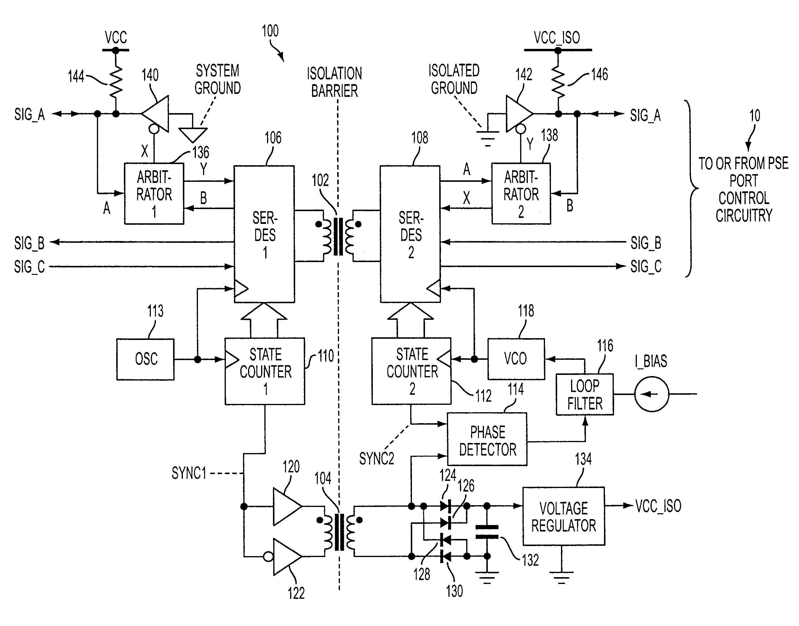
[0048]FIG. 3 illustrates exemplary signals that may be transferred through a PSE isolation circuit 100 of the present disclosure to and / or from an isolated PSE port control circuitry 10. In particular, the PSE isolation circuit 100 may be configured to provide passes for three groups of signals—SIG_A, SIG_B and SIG_C. The group SIG_A may include at least one bi-directional signal, such as a serial data (SDA) signal for an Inter-Integrated Circuit (I2C) bus or a System Management Bus (SMB).

[0049]The group SIG_B may include at least one unidirectional signal supplied from the isolated PSE port control circuitry 10 to a circuit, from which the PSE port control circuitry 10 is electrically isolated by the PSE isolat...


PUM


Abstract

A circuit for providing electrical isolation of Power Sourcing Equipment (PSE) circuitry from external circuitry in a Power over Ethernet (PoE) system has an inductive circuit for providing an isolation barrier to electrically isolate an isolated side of the isolation circuit from a non-isolated side of the isolation circuit. A signal path circuitry is configured for transferring bidirectional and / or unidirectional signals over the isolation barrier between respective nodes at the isolated and non-isolated sides.

Description

[0001]This application claims priority of provisional U.S. patent application No. 60 / 900,933 filed on Feb. 13, 2007 and entitled “SYSTEMS AND METHODS FOR SUPPORTING POWER OVER ETHERNET SYSTEM.”TECHNICAL FIELD[0002]This disclosure relates to power supply systems, and more particularly, to circuitry and methodology for isolating Power Sourcing Equipment (PSE) control circuitry in a Power over Ethernet (PoE) system.BACKGROUND[0003]Over the years, Ethernet has become the most commonly used method for local area networking. The IEEE 802.3 group, the originator of the Ethernet standard, has developed an extension to the standard, known as IEEE 802.3af, that defines supplying power over Ethernet cabling. The IEEE 802.3af standard defines a PoE system that involves delivering power over unshielded twisted-pair wiring from a PSE to a Powered Device (PD) located at opposite sides of a link. Traditionally, network devices such as IP phones, wireless LAN access points, personal computers and We...

Claims


Application Information

Patent Timeline
Patent Type & Authority Applications(United States)
IPC IPC(8): H04B3/54
CPCH04L12/10
Inventor ROBBINS, STEVEN ANDREW
Owner ANALOG DEVICES INT UNLTD
Why Eureka
Try Eureka