End cap connector for a light tube

a technology of end caps and light tubes, which is applied in the direction of discharge tubes, lighting support devices, coupling device connections, etc., can solve the problems of complex electrical connection between circuit boards and traditional dual-pin electrical contacts of fluorescent tubes, and the inability to retrofit specific-designed solid-state lighting fixtures

Active Publication Date: 2010-08-12
TYCO ELECTRONICS LOGISTICS AG (CH)
View PDF32 Cites 88 Cited by
  • Summary
  • Abstract
  • Description
  • Claims
  • Application Information

AI Technical Summary

Benefits of technology

[0009]In another embodiment, a lighting system is provided for connecting a solid state light tube to more than one type of socket connector where each type of socket connector has a different mating interface. The light tube has a circuit board with one or more solid state lighting devices mounted thereto and a lens covering the circuit board. The lighting system includes first and second end cap assemblies each having an end cap body having a lens engagement surface configured to engage the lens. Each of the first and second end cap assemblies have an end cap connector extending from the end cap body that holds contacts configured to be electrically connected to the circuit board and to the corresponding socket connector. The end cap body of the first end cap assembly defines a first mating interface configured to mate with a first type of socket connector and the end cap body of the second end cap assembly defines a second meeting interface configured to mate with a second type of socket conductor.

Problems solved by technology

However, a large number of traditional fluorescent fixtures are currently in use.
Replacement of these fixtures with specifically designed solid state lighting fixtures may be impractical or cost prohibitive for some people.
Problems arise in retrofitting the solid state light tubes to fit into traditional fluorescent lamps.
For example, the electrical connection between the circuit board and the traditional dual-pins that comprise the electrical contacts of a fluorescent tube may be complex and expensive to manufacture.
Manufacturing solid state light tubes in this manner is time-consuming, expensive and difficult.

Method used


Image

  • End cap connector for a light tube
  • End cap connector for a light tube
  • End cap connector for a light tube

Examples


Embodiment Construction

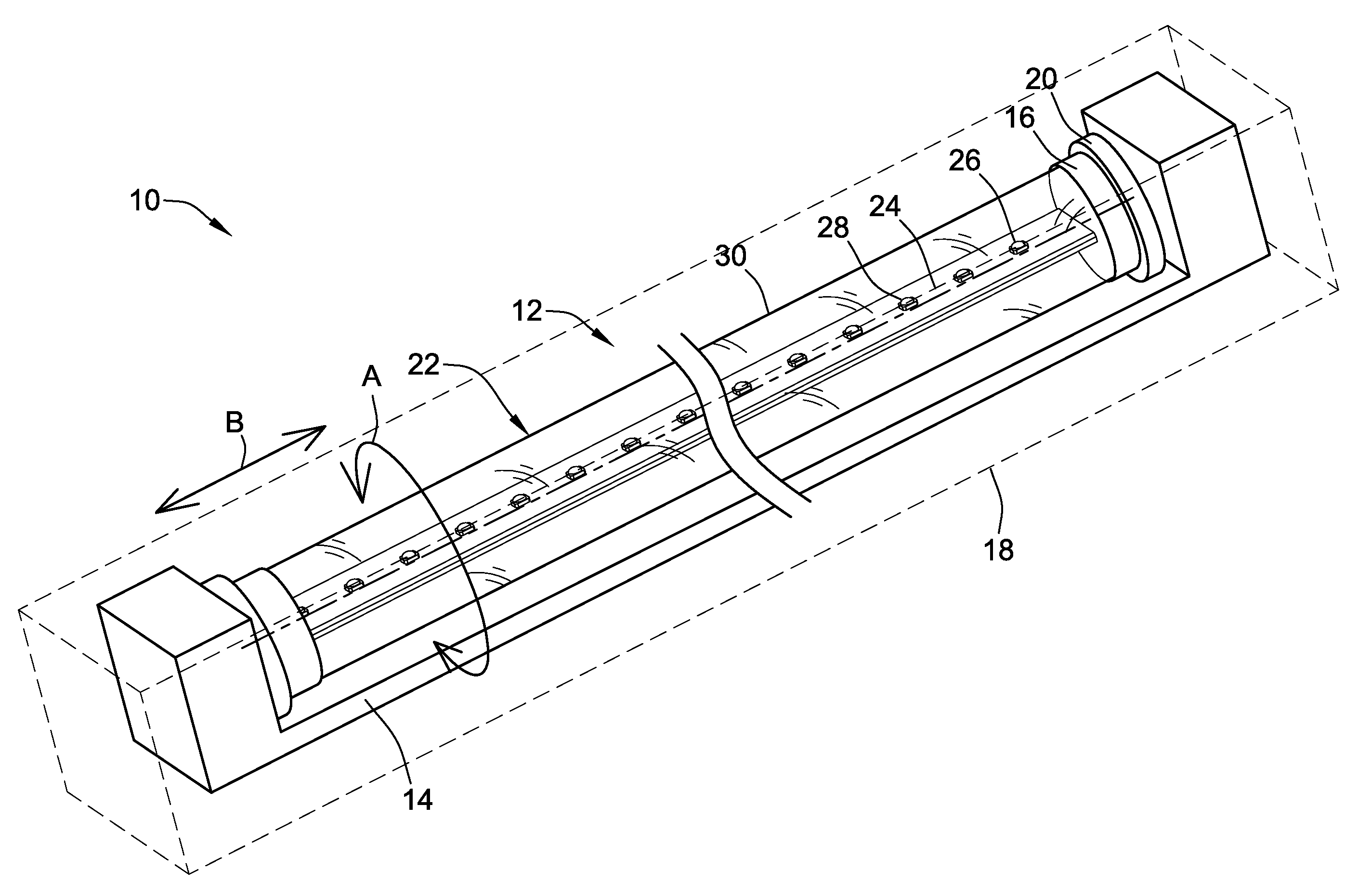
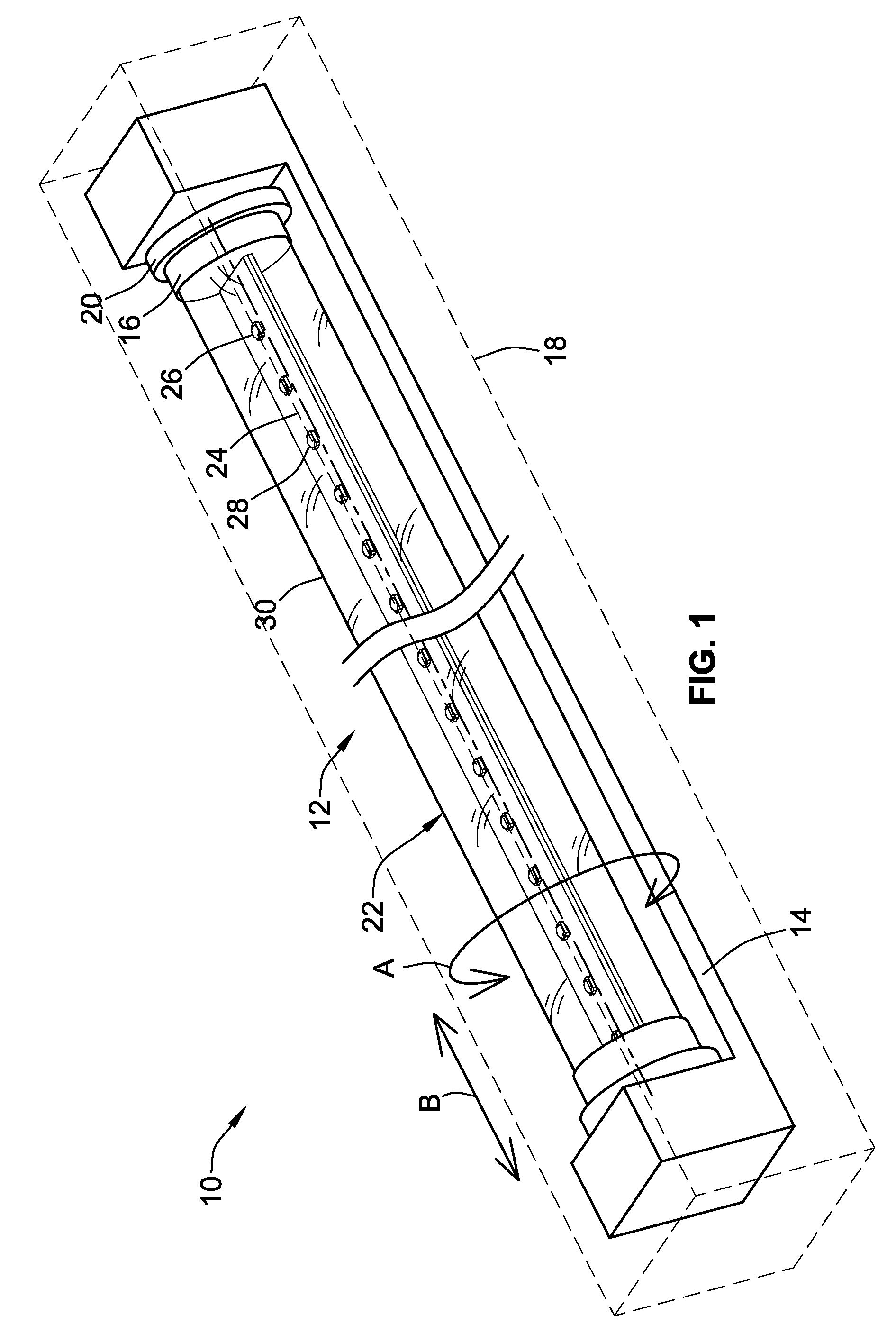
[0032]FIG. 1 illustrates a lighting system 10 utilizing a solid state light tube 12 that is assembled into a ballast 14 using end cap assemblies 16 formed in accordance with an exemplary embodiment. In an exemplary embodiment, the ballast 14, only a portion of which is illustrated in FIG. 1, may be traditional fluorescent lamp ballast that is used in a fluorescent lamp fixture 18 (represented schematically in phantom in FIG. 1). The ballast 14 receives power in from a traditional power supply, such as a line voltage from a building, and provides power to the light tube 12. The light tube 12 may be connected to socket connectors 20 of the ballast 14 in a traditional manner, such as by rotating the end cap assemblies 16 into the socket connectors 20, as shown by arrow A, or by inserting the end cap assemblies 16 linearly into the socket connectors 20, as shown by the arrow B, depending on the particular socket connector 20 type.

[0033]The light tube 12 extends between the end cap assem...


PUM


Abstract

An end cap assembly for a light tube that has a circuit board with one or more solid state lighting devices mounted thereto and a lens covering the circuit board includes an end cap body having a lens engagement surface configured to engage the lens and an external mating interface configured to mate with a socket connector of a fixture. An end cap connector extends from the end cap body. The end cap connector holds contacts having first mating portions configured to be electrically connected to the circuit board and second mating portions configured to be electrically connected to the socket connector.

Description

BACKGROUND OF THE INVENTION[0001]The subject matter herein relates generally to lighting assemblies, and more particularly, to an end cap assembly for a light tube.[0002]Solid state light sources, such as light-emitting diodes (“LEDs”), organic light emitting devices or other solid state sources, are now widely applied in a variety of lighting applications. The relatively high efficacy of LEDs (in lumens per watt) is the primary reason for their popularity. Power savings and extended lamp life are possible when LEDs are used to replace traditional fluorescent lighting. Solid state light tubes are in use to replace traditional fluorescent bulbs. The solid state light tubes are typically assembled into a light tube having a circuit board with a plurality of LEDs or other solid state light sources electrically connected thereto. The light tube may or may not include a thermal dissipation device. The light tube may be linear or some other shape, such as circular, U-shaped and the like. ...

Claims


Application Information

Patent Timeline
Patent Type & Authority Applications(United States)
IPC IPC(8): H01J61/94H01R12/00
CPCF21K9/175F21S8/031F21Y2101/02F21Y2103/003H01R33/08F21V29/777Y02B20/386H01R12/721F21V19/0035F21V19/004F21V23/06H01R33/94F21K9/272F21Y2103/10F21Y2115/10Y02B20/30
Inventor MOSTOLLER, MATTHEW EDWARDGINGRINCH, III, CHARLES RAYMONDDAILY, CHRISTOPHER G.WEBER, RONALD MARTINBROWN, RICKY EDWARD
Owner TYCO ELECTRONICS LOGISTICS AG (CH)
Why Eureka
Try Eureka