
Masking sound generating apparatus, masking system, masking sound generating method, and program

Active Publication Date: 2010-08-19
YAMAHA CORP
View PDF6 Cites 6 Cited by
  • Summary
  • Abstract
  • Description
  • Claims
  • Application Information

AI Technical Summary

Benefits of technology

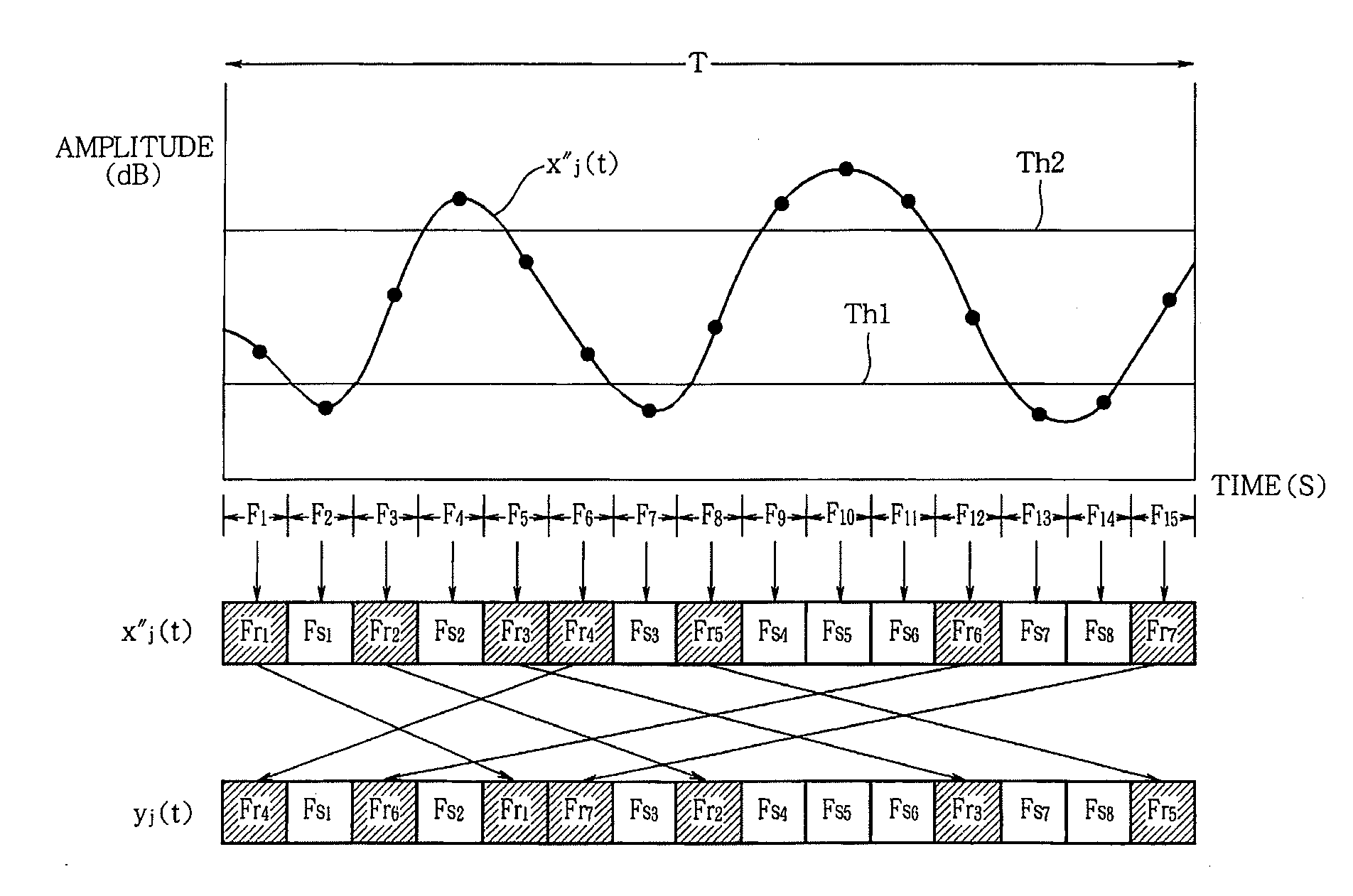
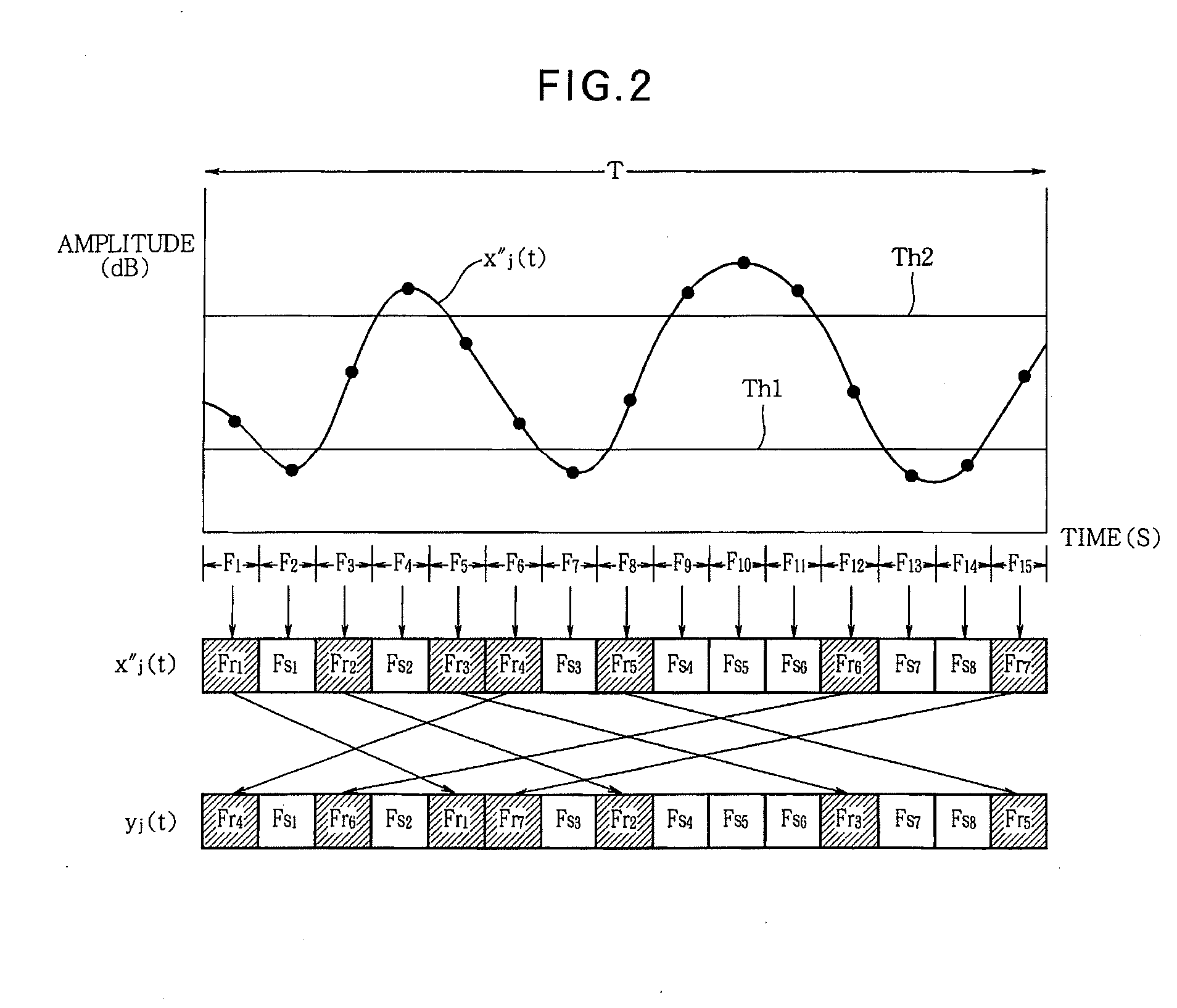
[0008]Here, the plurality of the envelope signals generated from the envelope signal generating part relate to intelligibility of sound represented by the audio signal. In this invention, the signal converting part randomizes the envelope signals so as to partially destroy an order of waveform which the envelope signal possesses (namely, disordering the waveform of the envelope signal), thereby reducing the intelligibility of the masking sound signal. According to the invention, it is possible to generate a masking sound that does not cause perception of noisy or unnatural sound.

Problems solved by technology

The masking effect is a phenomenon in which, when two types of sound signals having similar frequency component characteristics are propagated in the same space, it is difficult for a listener to identify the sound signals.
In this case, it is difficult to hear the target sound signal outside the room due to the masking effect since both the target sound signal and the masking sound signal which has frequency components close to those of the target sound signal are emitted outside the room.
However, since such a masking system simultaneously emits two types of sound signals, i.e., the target sound signal and the masking sound signal, a listener in the room may perceive noisy or unnatural sound, depending on the relation between the frequency components of the target sound signal and the frequency components of the masking sound signal.

Method used


Image

  • Masking sound generating apparatus, masking system, masking sound generating method, and program
  • Masking sound generating apparatus, masking system, masking sound generating method, and program
  • Masking sound generating apparatus, masking system, masking sound generating method, and program

Examples


Embodiment Construction

[0012]Embodiments of the invention will now be described with reference to the accompanying drawings.

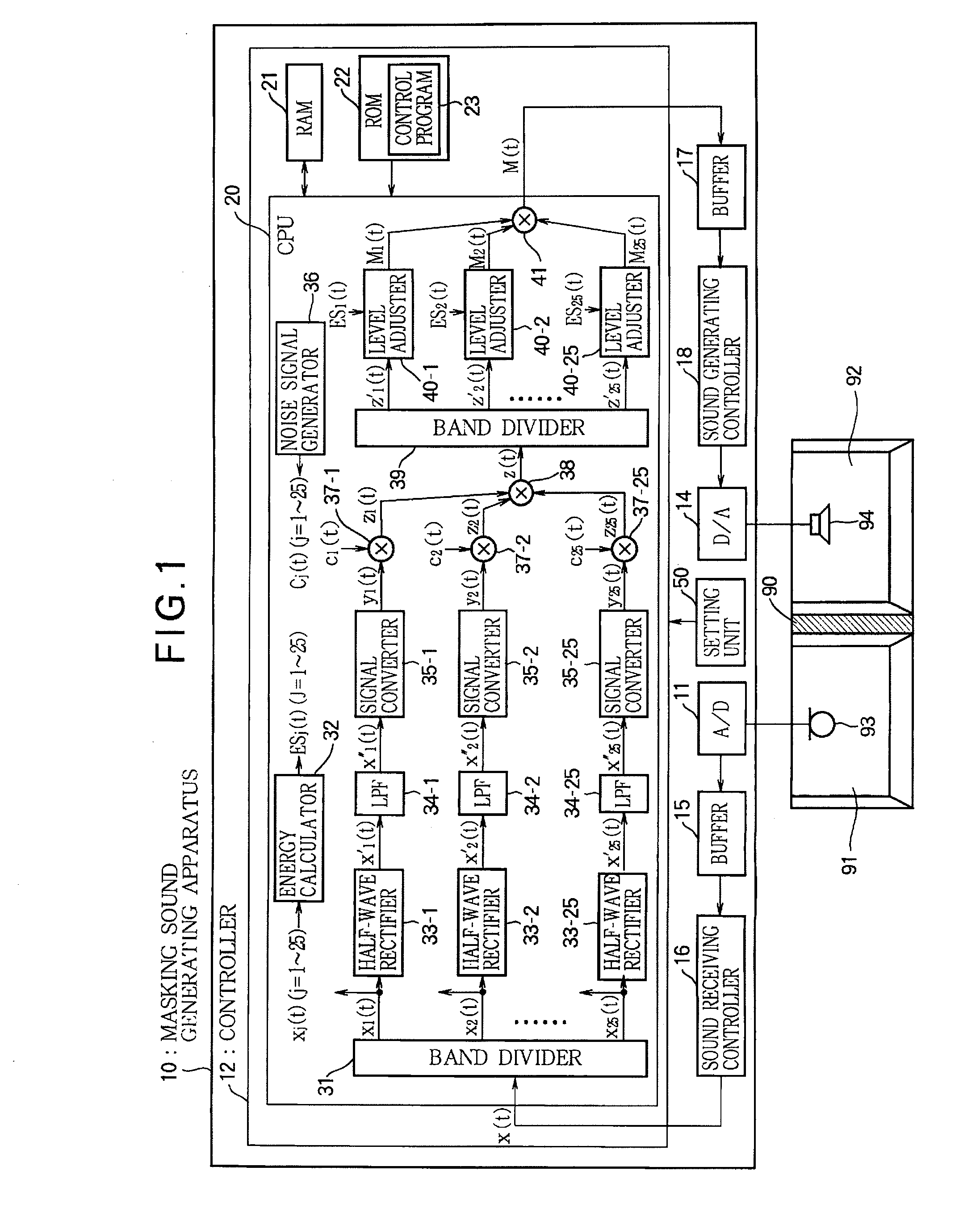
[0013]FIG. 1 is a block diagram illustrating a configuration of a masking system including a microphone 93, a speaker 94, and a masking sound generating apparatus 10 according to an embodiment of the invention. The masking sound generating apparatus 10 generates a different sound signal (which will be referred to as a “masking sound signal M(t)”), which makes it difficult to hear an original sound received in one room 91 among two rooms 91 and 92 divided by a wall 90, from a sound signal (which will be referred to as a “target sound signal x(t)”) corresponding to the sound received by the microphone 93 in the room 91 and outputs the generated masking sound signal M(t) to the other room 92 through the speaker 94.

[0014]An analog waveform signal of an original sound received by a microphone 93 fixed in the room 91 is input to an A / D converter 11 in the masking sound generating apparatus...


PUM


Abstract

In a masking sound generating apparatus, a band divider divides a target sound signal into a plurality of frequency bands to generate a plurality of band signals. An envelope signal generating part generates a plurality of envelope signals representing respective envelopes of the plurality of the band signals. A signal converter segments each of the plurality of the envelope signals into a plurality of frames, then specifies frames of segmented envelope signals which have an amplitude greater than a first threshold and less than a second threshold, and changes an order of the specified frames in an arrangement of the plurality of the frames. A multiplier multiplies each of the plurality of the envelope signals by a noise signal, each envelope signal having the order of the frames changed by the signal converter, and outputs the plurality of the envelope signals multiplied by the noise signal as individual band masking signals. An adder adds the individual band masking signals to output a masking sound signal capable of masking the target sound signal.

Description

BACKGROUND OF THE INVENTION[0001]1. Technical Field of the Invention[0002]The present invention relates to a technology for generating a masking sound to prevent an original sound from being overheard.[0003]2. Description of the Related Art[0004]The masking effect is a phenomenon in which, when two types of sound signals having similar frequency component characteristics are propagated in the same space, it is difficult for a listener to identify the sound signals. In one technology, overhearing of spoken sound is prevented using the masking effect. In this technology, a sound signal of a vocal sound generated in a room is collected as a target sound signal and is processed into a masking sound signal having frequency characteristics which do not allow the target sound signal to be perceived as a vocal sound, and the masking sound signal is then emitted outside the room. In this case, it is difficult to hear the target sound signal outside the room due to the masking effect since bo...

Claims


Application Information

Patent Timeline
IPC IPC(8): H04R3/02
CPCG10K11/175H04K3/825H04K2203/12H04K1/02H04K1/04H04K1/06H04K3/43H04K3/46G10K11/1752
Inventor TOHYAMA, MIKIOKOIKE, MAISHIMIZU, YASUSHI
Owner YAMAHA CORP
Learn More