Crop harvester

a harvester and crop technology, applied in the field of material handling, can solve the problems of crop shattering and excess maintenan

Inactive Publication Date: 2010-08-26
MARRS EVEN FLO HEADERS
View PDF40 Cites 11 Cited by
  • Summary
  • Abstract
  • Description
  • Claims
  • Application Information

AI Technical Summary

Problems solved by technology

This causes side draft on the fingers, resulting in excess maintenance.
Conventional full finger harvesters also employ a reel to force the crops into the header, which can cause crop shattering.

Method used


Image

  • Crop harvester
  • Crop harvester
  • Crop harvester

Examples


Embodiment Construction

[0015]The preferred embodiment and other embodiments, including the best mode of carrying out the invention, are hereby described in detail with reference to the drawings. Further embodiments, features and advantages will become apparent from the ensuing description or may be learned without undue experimentation. The figures are not drawn to scale, except where otherwise indicated. The following description of embodiments, even if phrased in terms of “the invention,” is not to be taken in a limiting sense, but describes the manner and process of making and using the invention. The coverage of this patent will be described in the claims. The order in which steps are listed in the claims does not indicate that the steps must be performed in that order.

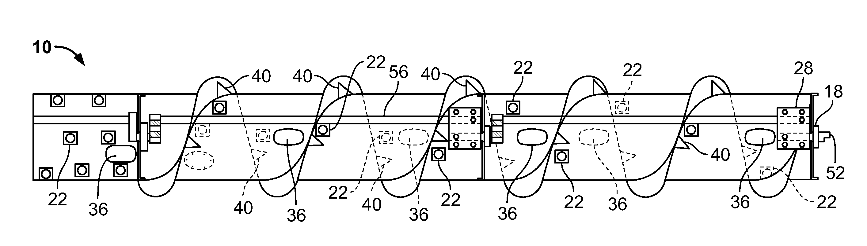
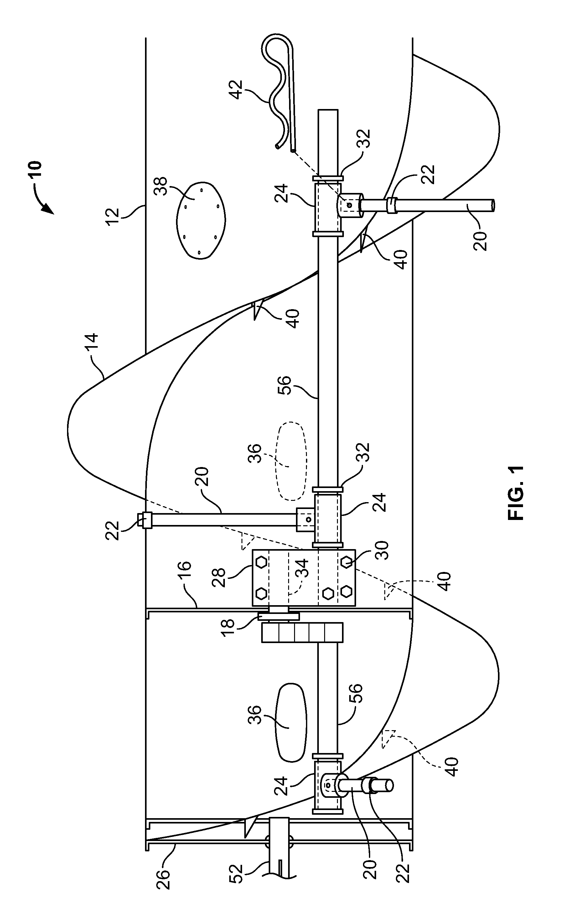
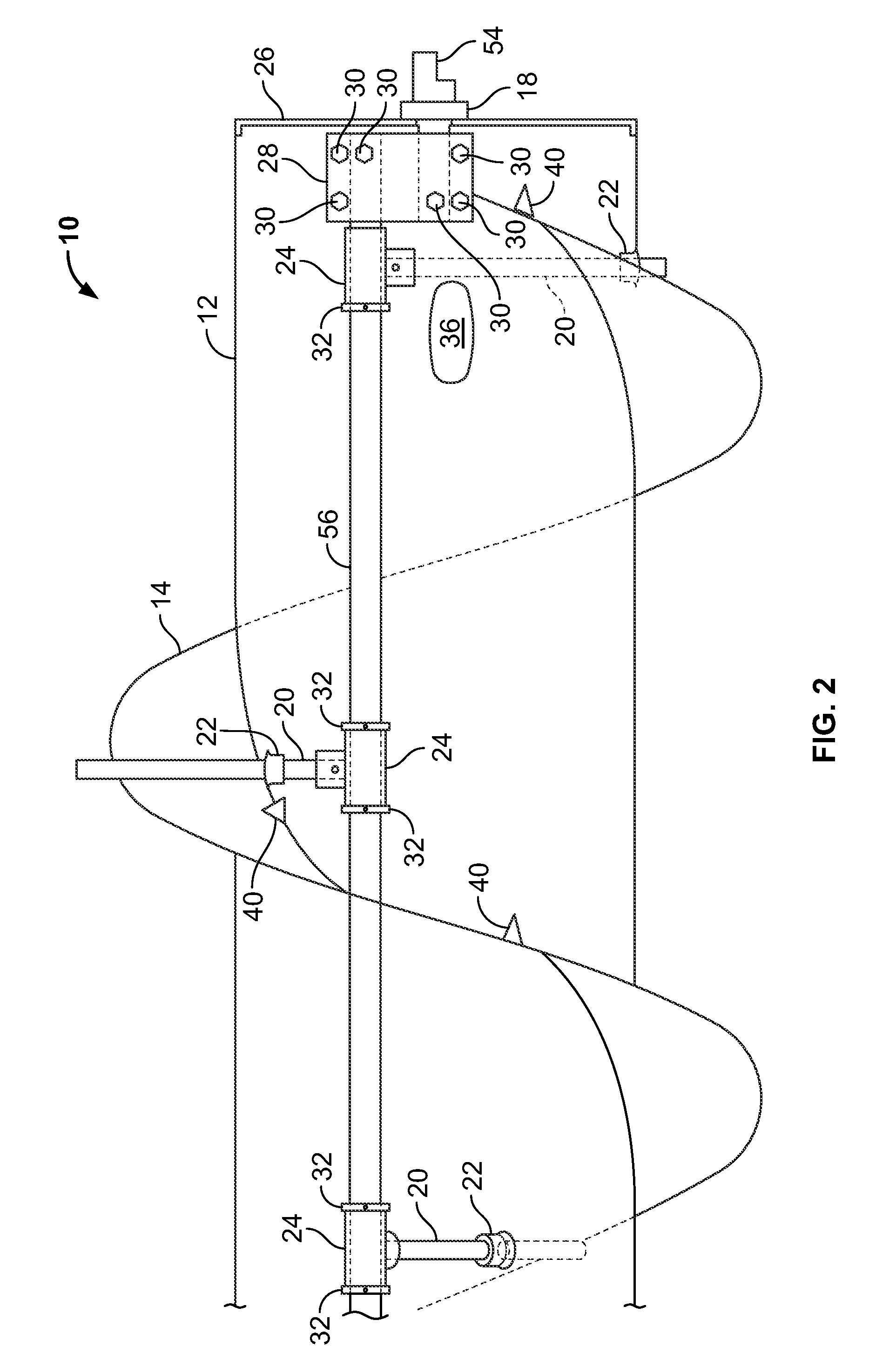
[0016]An embodiment of the invention can harvest beans with minimal auger wrapping and shattering. Reel shattering can be reduced to zero or near-zero.

[0017]An embodiment of the present invention locates longer fingers in the crop free ...


PUM


Abstract

A crop harvester includes: a rotatable auger tube having a gathering section; flighting disposed in a spiral pattern on the outer surface of the gathering section so that, when the auger tube is rotated, the flighting moves material within a perimeter of the flighting laterally and creates a neutral zone behind the flighting that is generally free of material; and gathering fingers disposed in the neutral zone that, when the auger tube is rotated, extend beyond the perimeter of the flighting to gather the material, tuck the material toward the auger tube, and then retract within the perimeter of the flighting.

Description

FILING DATE[0001]This application claims the benefit of the filing date of U.S. Patent Application No. 61 / 154,097, filed Feb. 20, 2009.BACKGROUND OF THE INVENTION[0002]The present invention generally relates to material handling and more specifically to a crop harvester.[0003]Full finger augers available now encourage auger wrapping in tuff or vine crops. They also have the gathering fingers timed parallel with the feeder fingers, so that both types of fingers extend toward the crops at the same time, even though the gathering fingers and finger fingers serve a totally different purpose. The auger-wrapping problem is so bad in vine crops, that manufacturers of full finger augers may recommend removing the center feeder section fingers and adding extension flighting over the feeder section to alleviate the problem.[0004]Conventional fingers located midway between flights are not timed to gather the crop and release it without being in competition with the flighting. This causes side ...

Claims


Application Information

Patent Timeline
Patent Type & Authority Applications(United States)
IPC IPC(8): A01D34/00
CPCA01D61/004
Inventor MARRS, WILLIAM R.
Owner MARRS EVEN FLO HEADERS
Why Eureka
Try Eureka