Measurement device

a measurement device and sensor technology, applied in the field of measurement devices, can solve the problems falsifications of measurement, and achieve the effect of reducing possible sensor transmission failures

Inactive Publication Date: 2006-02-09
DEERE & CO
View PDF5 Cites 9 Cited by
  • Summary
  • Abstract
  • Description
  • Claims
  • Application Information

AI Technical Summary

Benefits of technology

[0010] This configuration potentially reduces possible sensor transmission failures and falsifications of the measurement results. Output values of the sensor can be charted with reference to the ground and / or applied to regulate or set the working parameters of the harvesting machine. In a preferred embodiment, the sensor can be moved together with the surface between the first and second position to avoid changes in the relative positions of sensor and light-transmitting panel that could lead to measurement errors.
[0011] It is preferred to mount the surface, and advantageously also the sensor, at its or their end(s) lying in the direction of flow of the crop in the conveyor channel so as to rotate about an axis that extends perpendicular to the direction of flow. At the end(s) that lie(s) upstream from the flow direction, the surface, and advantageously also the sensor, is / are connected to the wall of the conveyor channel so as to be movable manually or by an activator, in order for the surface and / or the sensor to rotate about the axis and move between the first and second positions.
[0012] The device is appropriately driven to the second position by an activator that is activated by an outside force on a manual input from an operator or automatically. The device can be driven to the second position after the end of a certain time interval (e.g. after 10 minutes) or automatically after an implausible output value is detected from the sensor. An implausible output value of this kind exists, for example, when the output value of the sensor is constant for a certain time interval (e.g. 10 seconds) or when existence of crop is indicated when no crop is flowing through the conveyor channel, which can be shown by means of the operating state of the conveyor elements or by other sensors, e.g. a light beam. In a similar way, i.e. after the end of a certain time interval or by changing values of the sensor, the surface and possibly the sensor can be brought automatically into the first position.
[0013] It is advantageous for the sensor to work optically, especially in the near-infrared range, and especially in the reflection mode. The surface is then a pane that is transparent to the wavelength range used by the sensor. This pane consists advantageously of a relatively hard, wear-resistant material, diamond or sapphire glass. In other embodiments, the sensor can also work capacitatively or with microwaves or it can measure the electric resistance of the crop in order to determine its moisture.
[0014] The measurement device according to the invention can be used in stationary systems or on any harvesting machine in which the crop flows past a sensor or the sensor is moved past the crop, e.g. on a swath.
[0015] Further objects, features and advantages of this invention will become readily apparent to persons skilled in the art after a review of the following description, with reference to the drawings and claims that are appended to and form a part of this specification.

Problems solved by technology

This configuration potentially reduces possible sensor transmission failures and falsifications of the measurement results.

Method used


Image

  • Measurement device
  • Measurement device

Examples


Embodiment Construction

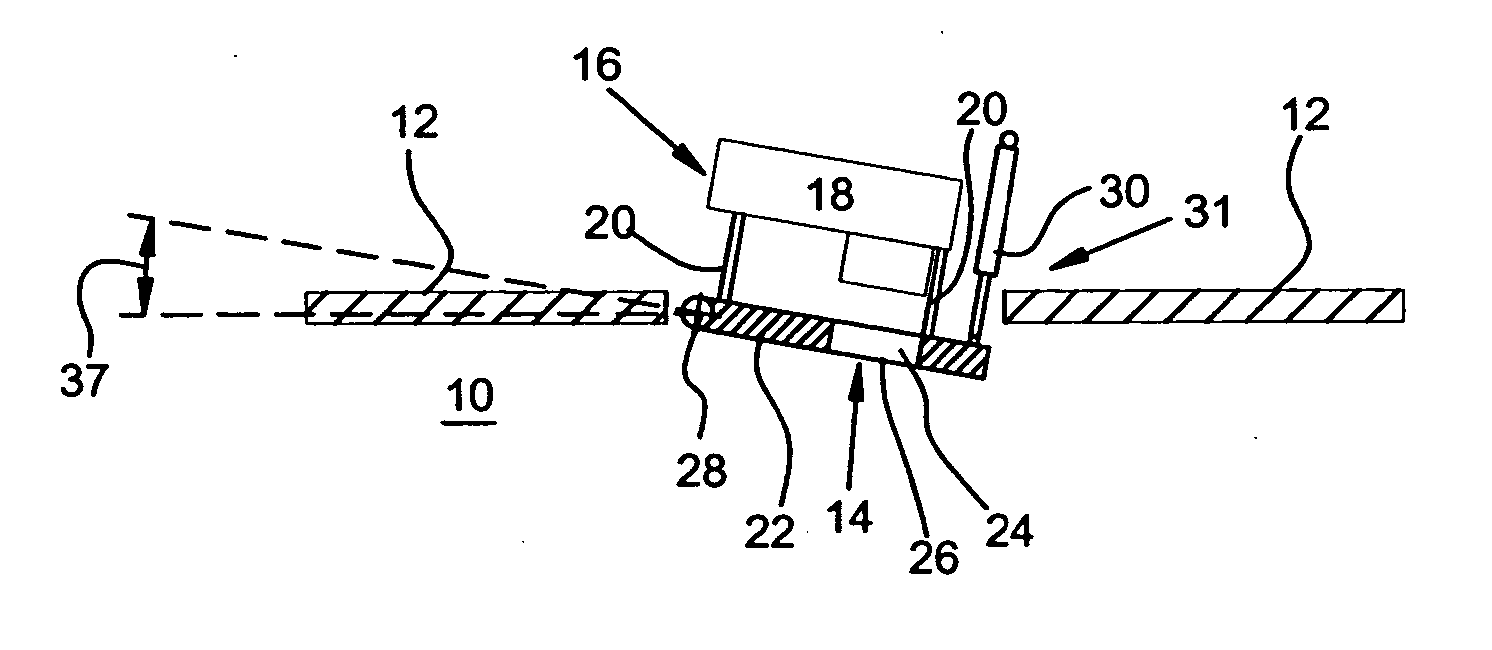
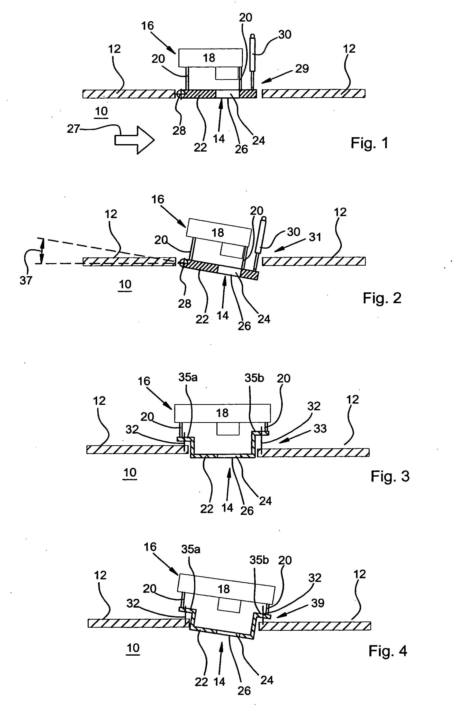
[0021] In the drawings, a conveyor channel of an automatic harvesting machine is shown by reference number 10, whereby this can involve, for example, a movable discharge device on a field chaff-cutter for sending chopped crop onto a vehicle according to the set ejection direction, the input channel of a ball press, or a region of a mowing thresher, in which threshed or unthreshed grain is conveyed, such as an inclined conveyer or a conveyor for filling the grain tank. The conveyor channel 10 is bordered by wall 12. The other walls of the conveyor channel 10 are omitted from the figures. In FIGS. 1 through 4, the crop in the harvesting operation moves horizontally through the conveyor channel 10 from left to right in the direction generally indicated by arrow 27.

[0022] In the wall 12, an opening 14 is provided, which serves to accept a measurement device, which is generally indicated by reference numeral 16. The measurement device 16 comprises, in both embodiments, a sensor 18, whic...


PUM


Abstract

A measurement device for detecting agricultural crops located within a conveyor channel. The measurement device includes a light-transmitting panel positioned adjacent to the conveyor channel and is configured to be movable between an operational position and a cleaning position. The measurement device includes a sensor positioned with respect to the light-transmitting panel so as to detect the agricultural crops in the conveyor channel through the light-transmitting panel. A harvesting machine is particularly adapted to utilize the measurement device.

Description

BACKGROUND [0001] 1. Field of the Invention [0002] The invention generally concerns a measurement device with a sensor for capturing the contents and / or characteristics of components of agricultural crops. [0003] 2. Related Technology [0004] Measurement devices suitable for analyzing the contents of organic material comprise, as a rule, sensors that work with light in the near-infrared wavelength rate in a reflection (NIR) or transmission (NIT) mode and are provided with light sources and optical analyzers. Several kinds of measurements devices of these types have been recommended for application to harvesting machines in order to capture and document the characteristics of the crop. [0005] Harvesting machines with these kinds of measurement devices have been described, for example, in WO 99 / 46974 A, WO 99 / 40419 A, WO 00 / 00818 A, EP 1 053 671 A, and in C. von Rosenberg et al: “A Rugged Near-infrared Spectrometer for the Real-time Measurement of Grains during Harvest,”Spectroscopy 15...

Claims


Application Information

Patent Timeline
Patent Type & Authority Applications(United States)
IPC IPC(8): G01J5/02
CPCA01D41/127A01D41/1271G01N2021/8592A01F15/08A01D43/085A01D41/1277
Inventor KORMANN, GEORGFLOHR, WERNER
Owner DEERE & CO
Why Eureka
Try Eureka