
Optical unit and projection-type liquid crystal display device using the same

a liquid crystal display and optical unit technology, applied in the field of optical units, can solve the problems of affecting the quality of image display on the screen, difficult to completely prevent the generation of such flaws and pinholes, and cannot be removed like dust, so as to achieve better image display and reduce the effect of optical units

Active Publication Date: 2010-08-26
MAXELL HLDG LTD
View PDF5 Cites 3 Cited by
  • Summary
  • Abstract
  • Description
  • Claims
  • Application Information

AI Technical Summary

Benefits of technology

[0010]The present invention has been made in view of the above problems, and it is an object of the invention to provide an optical unit which can reduce the effect on image projection of a flaw or a pinhole, if present on or in an inorganic output polarizing plate included in the optical unit, and can generate satisfactory image display, and a projection-type liquid crystal display device using the optical unit.
[0015]The present invention can provide an optical unit and a projection-type liquid crystal display device using the optical unit. The optical unit can reduce, even if an output polarizing plate included therein has a defect such as a flaw or a pinhole, the effect of such a flaw or a pinhole on image projection on the screen compared with when an output polarizing plate of a related art is used and can provide better image display than before.

Problems solved by technology

If an output polarizing plate disposed immediately downstream of a liquid crystal panel has such flaws or pinholes, which are free of polarization, they will be projected as bright spots on the screen to degrade the quality of image display on the screen.
During a manufacturing process of inorganic polarizing plates, it is difficult to completely prevent the generation of such flaws and pinholes.
Once a flaw or a pinhole is formed on or in an inorganic polarizing plate, it cannot be removed like dust.
It is not possible to remove a flaw or a pinhole by blowing air using a fan.

Method used


Image

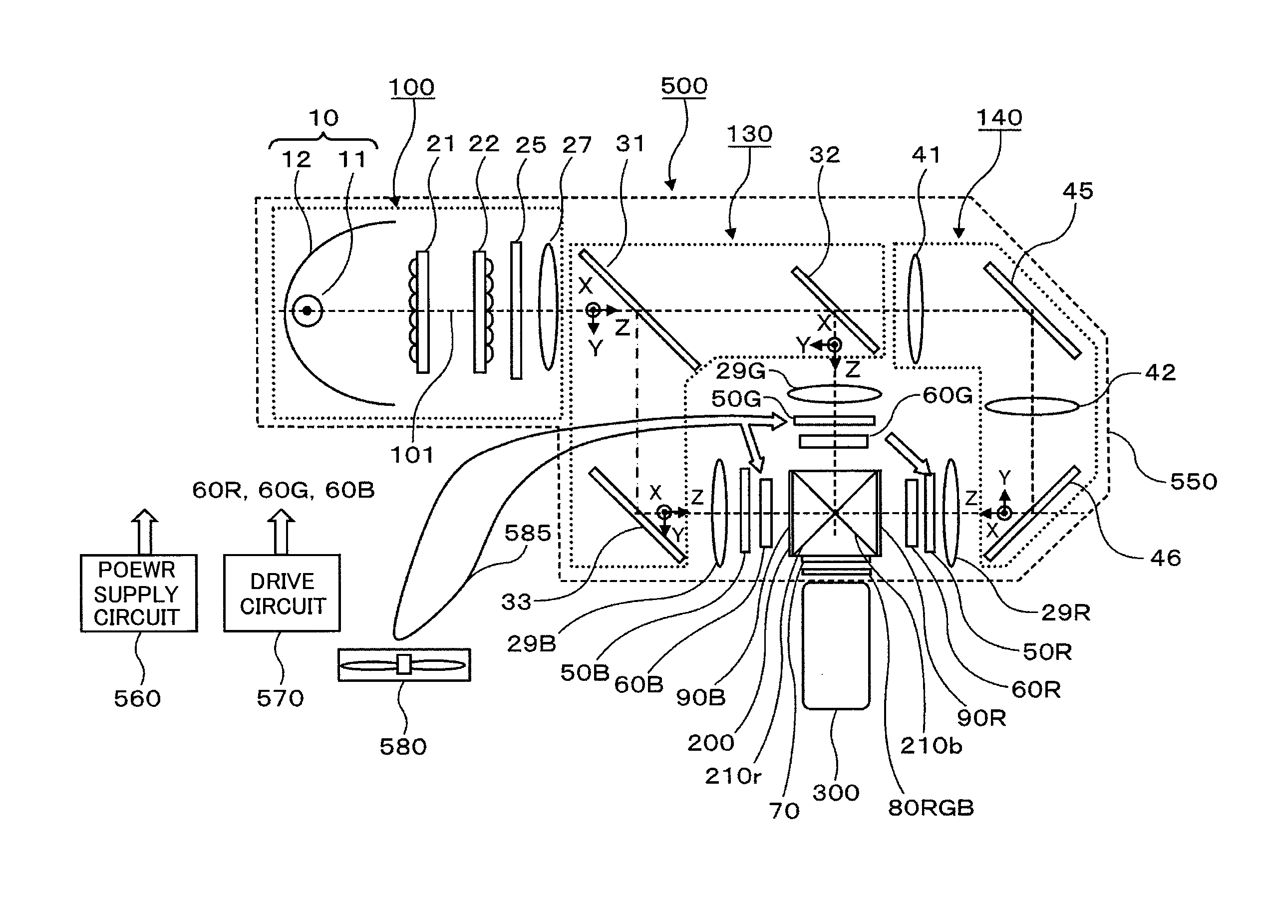
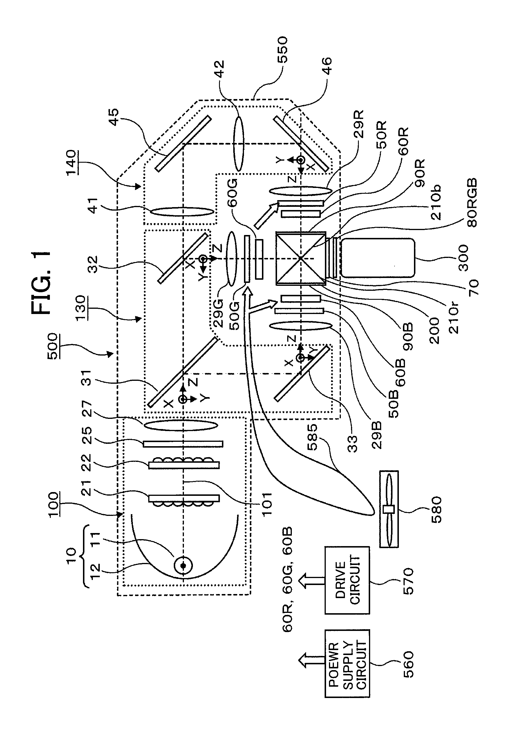
  • Optical unit and projection-type liquid crystal display device using the same
  • Optical unit and projection-type liquid crystal display device using the same
  • Optical unit and projection-type liquid crystal display device using the same

Examples


first embodiment

[0023]First, an optical unit and a projection-type liquid crystal display device using the optical unit according to a first embodiment of the present invention will be described, then a configuration around liquid crystal panels will be described in detail.

[0024]FIG. 1 is a diagram showing an overall configuration of the optical unit and the projection-type liquid crystal display device according to the first embodiment of the invention. In FIG. 1, each element associated with a color-specific light path is denoted by a reference numeral postfixed with a corresponding letter R, G, or B. Other elements are each denoted by a reference numeral without any color-representing postfix. Also, for the clarification of polarization directions, a Cartesian coordinate system is employed. Namely, in this specification, an optical axis 101 is defined as a Z axis; an axis extending perpendicularly to the Z axis in a plane parallel to the plane of FIG. 1 is defined as a Y axis; and an axis extend...

second embodiment

[0047]In the first embodiment described in the foregoing, the output polarizing plate 80RGB used commonly for R, G, and B light is disposed on the output side of the photosynthesis prism 200. In a second embodiment, an output polarizing plate 80RG used commonly for R light and G light is disposed on the output side of the photosynthesis prism 200 and an output polarizing plate 80B for B light is disposed immediately downstream of the liquid crystal panel 60b. The reasons for this are as follows.

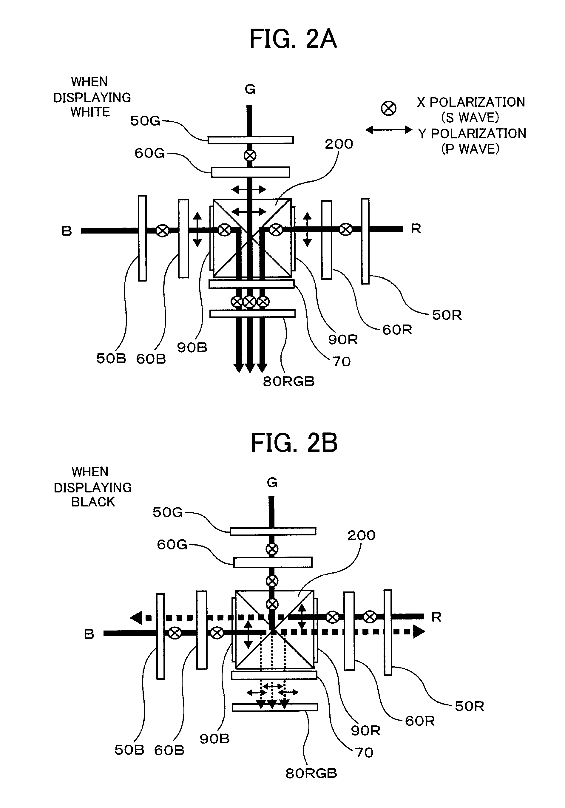
[0048](1) When, as shown in FIG. 2B, displaying black with the output polarizing plate 80RGB disposed on the output side of the photosynthesis prism 200, the B light and the R light passes the dichroic films formed in the photosynthesis prism 200 and most of the B light and the R light leaks into the opposing liquid crystal panels 60R and 60B, respectively. This causes the liquid crystal panels 60R and 60B to be heated, making it necessary to devise a measure to cool them.

[0049](2) Of the lig...


PUM

PropertyMeasurementUnit
wavelength bandsaaaaaaaaaa
colorsaaaaaaaaaa
wavelength bandaaaaaaaaaa

Abstract

An optical unit is provided which includes inorganic polarizing plates used as output polarizing plates. Even if a defect such as a flaw or a pinhole is present in the polarizing plate, the defect is not projected on the display screen. Instead of output polarizing plates for liquid crystal panels for R, G, and B, a common polarizing plate for R, G, and B is disposed on the output side of a photosynthesis prism. A color selective polarization rotator which rotates the polarization of light of a selected wavelength band is disposed between the photosynthesis prism and the common polarizing plate. Or, alternatively, instead of output polarizing plates for R and G to be individually disposed along with an output polarizing plate for B, a common output polarizing plate for R and G is disposed on the output side of the photosynthesis prism.

Description

CLAIM OF PRIORITY[0001]The present application claims priority from Japanese patent application serial No. JP 2009-042460, filed on Feb. 25, 2009, the content of which is hereby incorporated by reference into this application.BACKGROUND OF THE INVENTION[0002](1) Field of the Invention[0003]The present invention relates to an optical unit which, according to a video signal, intensity-modulates light emitted from a light source using transmissive liquid crystal panels and which enlarges and projects optical images formed on the liquid crystal panels, and more particularly, to the structure of output polarizing plates of the transmissive liquid crystal panels.[0004](2) Description of the Related Art[0005]A projection-type display device has been known which includes an optical unit accommodated in an enclosure together with a drive circuit, a power supply circuit, and a cooling fan, the optical unit intensity-modulating, by using light valves according to a video signal, light emitted ...

Claims


Application Information

Patent Timeline
Patent Type & Authority Applications(United States)
IPC IPC(8): G02F1/1335
CPCG03B21/14G03B21/2073G03B33/12
Inventor KIMURA, NOBUYUKI
Owner MAXELL HLDG LTD
Learn More