Root cause analysis by correlating symptoms with asynchronous changes

a root cause and symptom technology, applied in the field of information technology problem analysis, can solve problems such as the most common problems

Inactive Publication Date: 2010-08-26
IBM CORP
View PDF7 Cites 82 Cited by
  • Summary
  • Abstract
  • Description
  • Claims
  • Application Information

AI Technical Summary

Benefits of technology

[0008]One or more embodiments of the invention or elements thereof can be implemented in the form of a computer product including a tangible computer readable recordable storage medium with computer usable program code for performing the method steps indicated. Furthermore, one or more embodiments of the invention or elements thereof can be implemented in the form of an apparatus including a memory and at least one processor that is coupled to the memory and operative to perform exemplary method steps. Y...

Problems solved by technology

These changes are applied to fix existing problems and/or improve performance in the system, but they themselves may induce one or more of the following problems:New bug(s) and/or problem(s) due to mismatch between real environment and test environment.M...

Method used


Image

  • Root cause analysis by correlating  symptoms with asynchronous changes
  • Root cause analysis by correlating  symptoms with asynchronous changes
  • Root cause analysis by correlating  symptoms with asynchronous changes

Examples


example

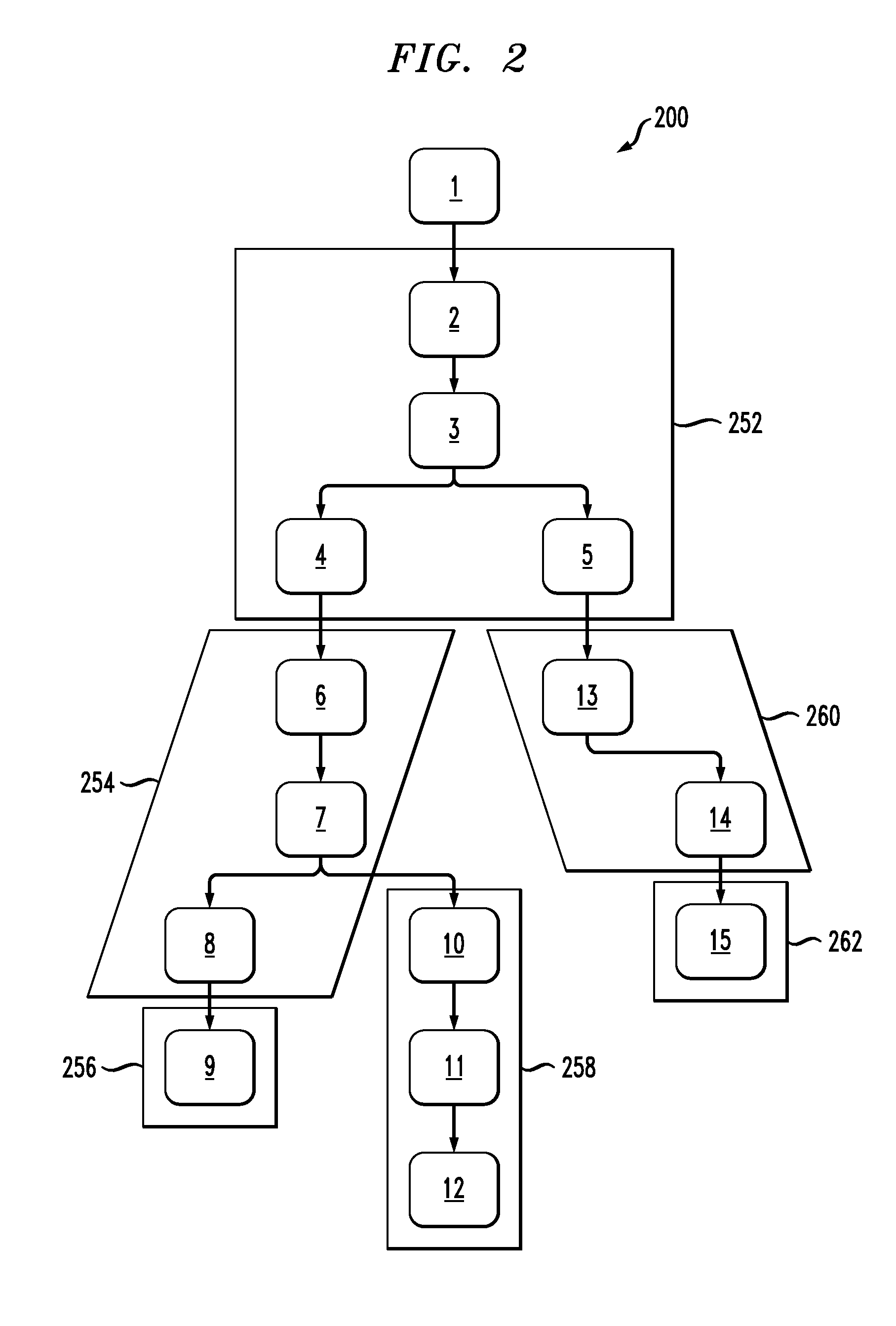
[0065]Consider the transaction call graph 200 shown in FIG. 2. As noted, each numbered box 1-15 represents a component. This call graph contains three transactions T1, T2 and T3. For each of the transactions, the following are the subset of components that each one of them accesses:

T1={2,3,4,6,7,8,9}, T2={2,3,5,13,14,15}, T3={2,3,4,6,7,10,11,12}.

[0066]Assume that transaction T1 is failing whereas T2 and T3 are successful. Assume that the transaction T1 has a change set T1c applicable on it such that:

T1c{C1, C2, C3, C4, C5,}.   (11)

Similarly, T2c={C1} and T3c={C2,C3}. There may be some other changes present which are applicable only to T2 or T3 but there is no need to be interested in those changes as those are definitely not the root cause changes for transaction T1.

Now, based on this set T1c can be divided in three sub-sets, namely:

{C1}, {C2,C3} and {C4,C5}, the union of which makes the set T1c. As per the theorem in the immediately preceding section, do not consider any further su...


PUM


Abstract

An indication of a problem in at least one component of a computing system is obtained. A relevant change set associated with a directed dependency graph is analyzed. The computing system is configured to proactively overcome a root cause of the problem. The relevant change set includes a list of past changes to the computing system which are potentially relevant to the problem. The directed dependency graph includes dependency information regarding given components of the computing system invoked by transactions in the computing system. The analyzing includes identifying at least one of the past changes to the computing system that is the root cause of the problem.

Description

FIELD OF THE INVENTION[0001]The present invention relates to the electrical, electronic and computer arts, and, more particularly, to problem analysis for information technology (IT) and the like.BACKGROUND OF THE INVENTION[0002]There is a great deal of work done in distributed systems to pinpoint the root cause of an anomaly as quickly as possible, once the anomaly is detected by the system administrator. The work in this area is broadly classified as Problem Determination (PD) work. In most PD work, once an anomaly is detected, the system looks at the set of recent events to associate them with a failure. If the root cause event has happened asynchronously (that is, in the past), only the symptom events are seen, and the real root cause event (or events) is / are not even considered. Frequently, these root cause events are change events that are done deliberately by the system administrator in an asynchronous manner. Examples of these changes are applying a new patch of software, up...

Claims


Application Information

Patent Timeline
IPC IPC(8): G06F11/07G06N5/02
CPCG06F11/079G06F11/0709
Inventor AGARWAL, MANOJ K.GUPTA, MANISHMADDURI, VENKATESWARA R.
Owner IBM CORP
Why Eureka
Try Eureka