Image capturing device and method for adjusting photographing angle thereof

a technology of image capturing and image capturing device, which is applied in the field of image capturing device and a method for adjusting the photographing angle of the image capturing device, can solve the problems of time-consuming and imprecise methods

Active Publication Date: 2010-09-02
CLOUD NETWORK TECH SINGAPORE PTE LTD
View PDF7 Cites 32 Cited by
  • Summary
  • Abstract
  • Description
  • Claims
  • Application Information

AI Technical Summary

Problems solved by technology

Images captured by an image capturing device, such as a camera, may be skewed at an angle causing undesirable results.
As a result, an operator of the ca...

Method used


Image

  • Image capturing device and method for adjusting photographing angle thereof
  • Image capturing device and method for adjusting photographing angle thereof
  • Image capturing device and method for adjusting photographing angle thereof

Examples


Embodiment Construction

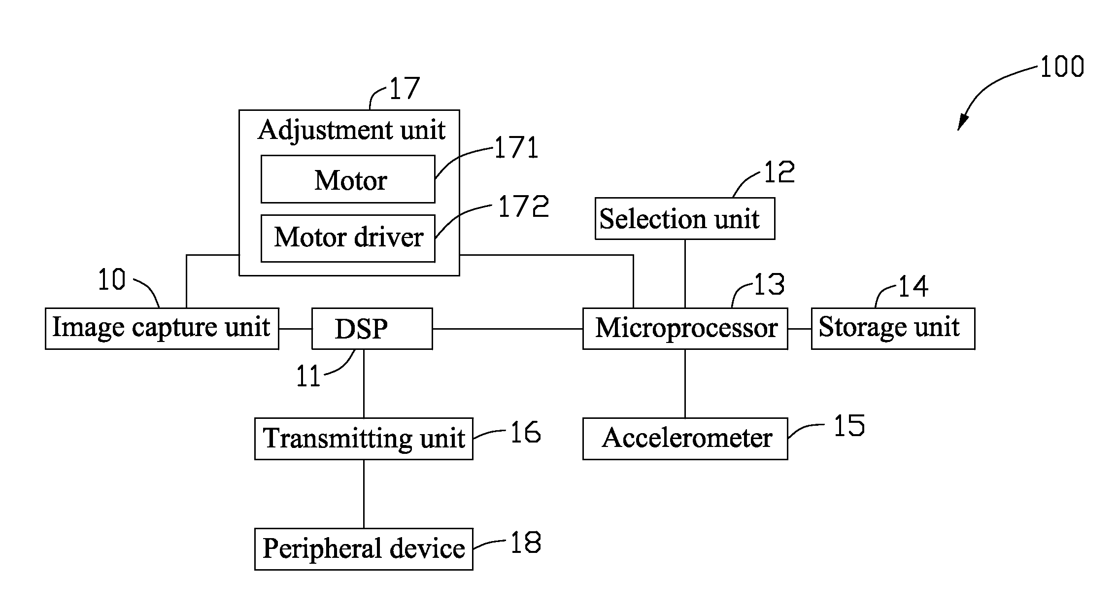
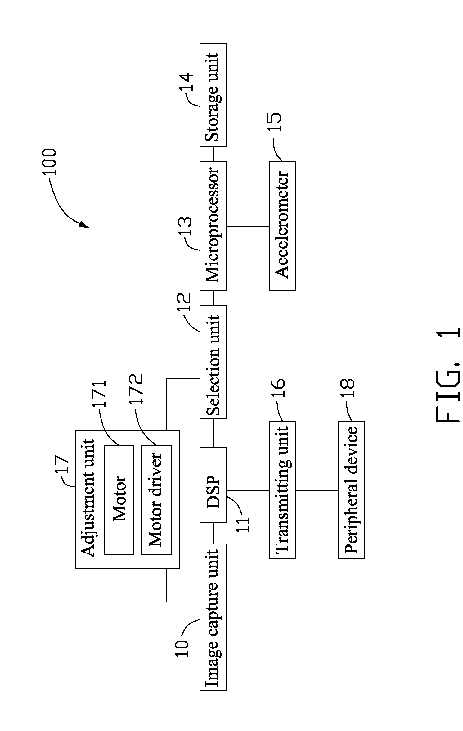
[0009]Referring to FIG. 1, a first exemplary embodiment of an image capturing device 100 includes an image capture unit 10, a digital signal processor (DSP) 11, a selection unit 12, a microprocessor 13, a storage unit 14, an accelerometer 15, a transmitting unit 16, and an adjustment unit 17. The image capture unit 10 includes a plurality of photographing lenses and a charge coupled device (CCD). The adjustment unit 17 includes a motor 171 connected to the image capture unit 10, and a motor driver 172. The motor driver 172 drives the plurality of photographing lenses and the CCD to adjust a photographing angle of the image capture unit 10.

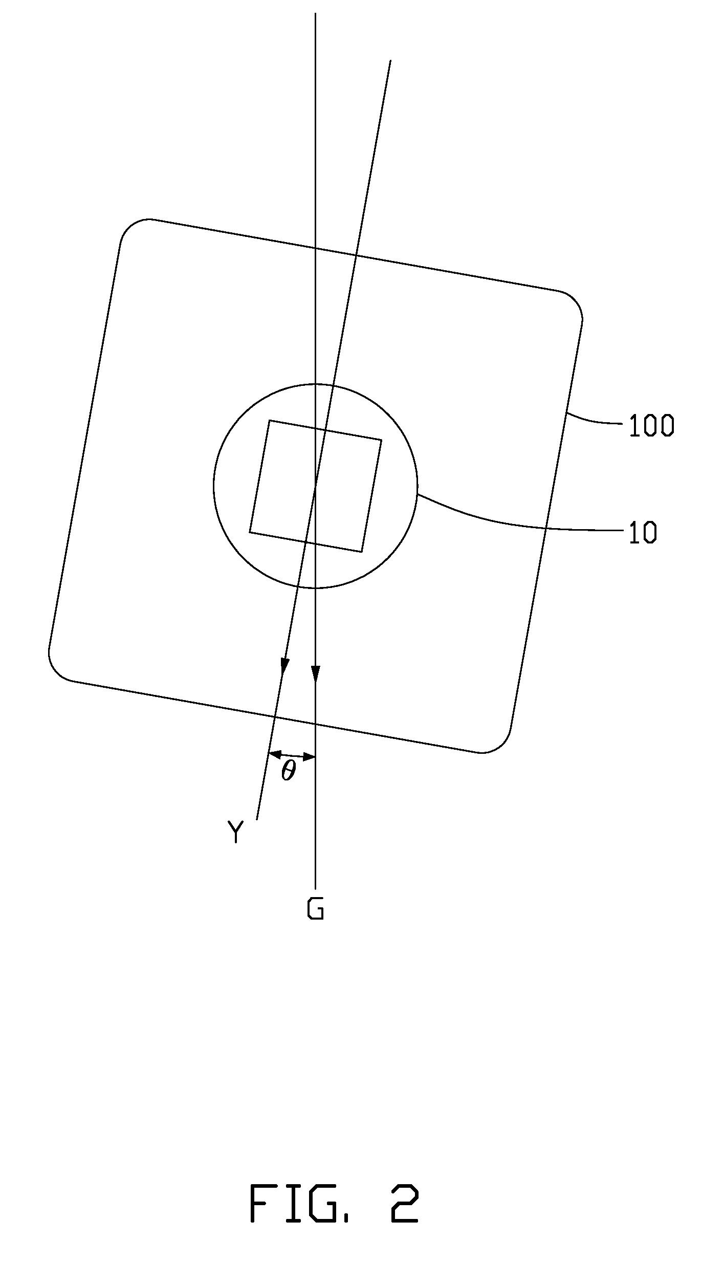
[0010]The image capture unit 10 is used for capturing images and outputting images in the form of data to the DSP 11. The accelerometer 15 is used for detecting an angle θ between a downward vertical axis Y of the image capture unit 10 and the direction G of the gravitational field, shown as FIG. 2, to output an adjustment signal α. It is understoo...


PUM


Abstract

A image capturing device includes an image capture unit, a digital signal processor (DSP), a selection unit, an adjustment unit, a microprocessor, a storage unit, and a accelerometer. The image capture unit photographs a subject to output image data representing the subject to the DSP. The accelerometer detects an angle between a vertical axis of the image capture unit and the direction of the gravitational field to output an adjustment signal. The microprocessor outputs an adjustment value after comparing the adjustment signal with a reference adjustment value preset in the storage unit. When a first photograph angle adjustment manner is selected by the selection unit, the DSP adjusts the image data according to the adjustment value. When a second photograph angle adjustment manner is selected by the selection unit, the adjustment unit adjusts photographing angle of the image capture unit according to the adjustment value.

Description

BACKGROUND[0001]1. Technical Field[0002]The present disclosure relates to image capturing devices, and particularly to an image capturing device and a method for adjusting a photographing angle of the image capturing device.[0003]2. Description of the Related Art[0004]Images captured by an image capturing device, such as a camera, may be skewed at an angle causing undesirable results. As a result, an operator of the camera may have to capture the images again or use digital photography software to amend the problem. However, these methods may be time-consuming and imprecise.BRIEF DESCRIPTION OF THE DRAWINGS[0005]FIG. 1 is a block diagram of a first exemplary embodiment of an image capturing device.[0006]FIG. 2 is a schematic diagram of an angle between a vertical axis of the image capture unit in FIG. 1 and the direction of the gravitational field.[0007]FIG. 3 is a block diagram of a second exemplary embodiment of an image capturing device.[0008]FIG. 4 is a flowchart of an exemplary...

Claims


Application Information

Patent Timeline
IPC IPC(8): H04N5/228
CPCG03B17/02H04N5/232H04N5/2259H04N23/58H04N23/60
Inventor LEE, HOU-HSIENLEE, CHANG-JUNGLO, CHIH-PING
Owner CLOUD NETWORK TECH SINGAPORE PTE LTD
Why Eureka
Try Eureka