Blind Spot Detection System

a detection system and blind spot technology, applied in the direction of mirrors, instruments, mountings, etc., can solve the problems of blind spot proximate the vehicle, the driver does not have a view of the alien vehicle, and the driver is likely to catch the driver's attention

Inactive Publication Date: 2010-09-02
FORD GLOBAL TECH LLC
View PDF27 Cites 34 Cited by
  • Summary
  • Abstract
  • Description
  • Claims
  • Application Information

AI Technical Summary

Benefits of technology

[0010]An advantage presented is that the mirror is returned to the position at which the driver had initially positioned the mirror, the

Problems solved by technology

However, a blind spot exists such that the driver does not have a view of alien vehicle 6 without craning his/her neck around.
One issue is how to use such information to improve the driver's knowledge about such vehicles detected in the blind spot.
Thus, even though the driver may not be looking into the mirror prior to, or at the time

Method used


Image

  • Blind Spot Detection System
  • Blind Spot Detection System
  • Blind Spot Detection System

Examples


Embodiment Construction

[0018]As those of ordinary skill in the art will understand, various features of the embodiments illustrated and described with reference to any one of the Figures may be combined with features illustrated in one or more other Figures to produce alternative embodiments that are not explicitly illustrated or described. The combinations of features illustrated provide representative embodiments for typical applications. However, various combinations and modifications of the features consistent with the teachings of the present disclosure may be desired for particular applications or implementations. Those of ordinary skill in the art may recognize similar applications or implementations whether or not explicitly described or illustrated.

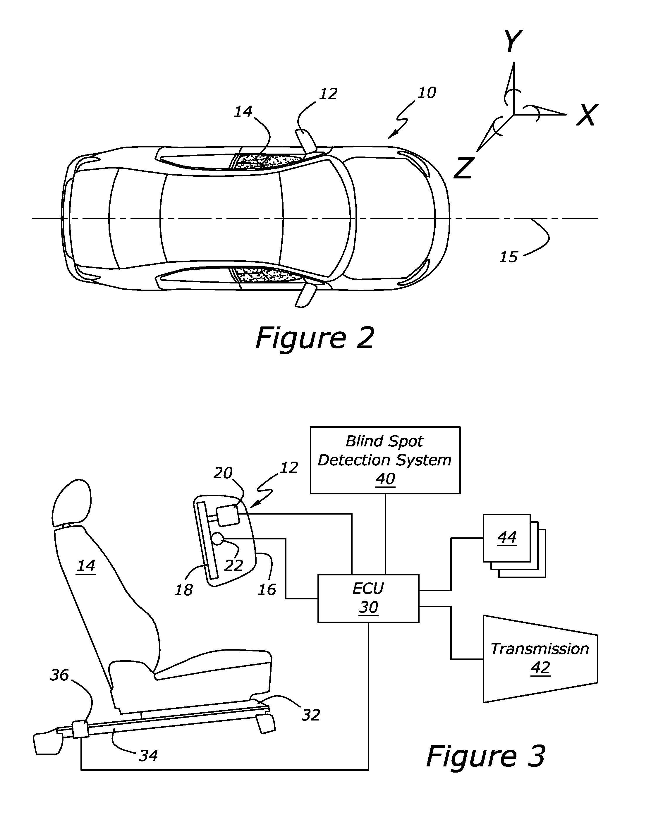
[0019]A plan view of a vehicle 10 is shown in FIG. 2. The vehicle has a left side mirror 12 and a driver's seat 14. In FIG. 2, mirror 12 and seat 14 are shown for a left side drive vehicle. The discussion in relation to FIG. 2 refers to left side mirro...


PUM


Abstract

A method and system to control a side mirror are disclosed in which a blind spot detector is used to determine whether an alien vehicle is present in a blind spot of a host vehicle. A sensor proximate a driver's seat detects whether the seat is in a first range or a second range. The side mirror is rotated a first predetermined angle when the alien vehicle is detected and the seat is in the first range; and the side mirror is rotated a second predetermined angle when the alien vehicle is detected and the seat is in a second range.

Description

CROSS-REFERENCE TO RELATED APPLICATIONS[0001]This application is a Continuation-in-Part of and commonly assigned U.S. patent application Ser. No. 12 / 059,267 filed May 31, 2008 entitled System, Apparatus and Method for Active Mirrors With Blind Spot Detection. The application has now published as U.S. 2009 / 024474 A1 and is incorporated herein by reference in its entirety.BACKGROUND[0002]1. Technical Field[0003]The disclosure relates to alerting a driver of an automotive vehicle as to the presence of an object in the vehicle's blind spot.[0004]2. Background Art[0005]Mirror systems are provided on automotive vehicles to aid the operator of the vehicle in viewing other vehicles while merging, lane changing, turning, reversing, etc. Mirrors can provide a view of the vehicles and objects in the vicinity of the operator's vehicle. However, the effectiveness of that view depends on alignment of the mirrors. It is known in the art, through customer interviews, car clinics, and survey comment...

Claims


Application Information

Patent Timeline
IPC IPC(8): G02B7/198
CPCB60R1/025B60R2300/301B60R1/081B60R1/072
Inventor CUDDIHY, MARK A.RAO, MANOHARPRASAD K.SCHONDORF, STEVEN YELLINSCHONDORF, KRISTIN MARIE
Owner FORD GLOBAL TECH LLC
Why Eureka
Try Eureka