Nasal Cannula Assembly

a cannula and assembly technology, applied in the field of nasal cannula assembly, can solve the problems of inability to provide a seal and nasal cpap, the problem of not solving the problem, and the cost of most devices used to treat sleep apnea is high, and the problem of repeat use is difficult,

Inactive Publication Date: 2010-09-09
JEMI AIRWAY MANAGEMENT
View PDF7 Cites 60 Cited by
  • Summary
  • Abstract
  • Description
  • Claims
  • Application Information

AI Technical Summary

Benefits of technology

[0018]Responsive to the foregoing challenges, Applicant has developed an innovative system and method for providing CPAP in patients while overcoming some of the limitations of known devices. An embodiment of the present invention is a nasal cannula assembly comprising a formable bridge, at least one nasal insert, at least one gas supply tube, a shape-retaining malleable element disposed in the bridge, and an op site dressing, wherein the gas supply tube is in communication with the bridge, the bridge is in communication with the nasal insert, and the op site dressing is in communication with the bridge. The malleable material may be a metal and / or a plastic. The nasal insert may be slightly flared and / or comprise a non-compressible bead disposed on the nasal insert. The op site dressing may comprise an adhesive backing.

Problems solved by technology

Most devices used to treat sleep apnea are expensive, cumbersome and designed for repeat use; therefore, they are not used in the operating room, emergency room, or critical care areas.
Such a device would overcome the inherent problem of existing nasal cannulae, which are designed to loosely fit in the nares and cannot easily contour to the face making it difficult to provide a seal and nasal CPAP.
None of these approaches has solved the problems—discussed.
Use of these approaches have been shown to irritate or otherwise damage the inside of the nares.
Unfortunately, this is somewhat cumbersome to apply, may be anxiety provoking and may impede the performing the operative procedure.
This approach also does not lend itself to use in the emergency room or other critical areas.
This overcomes the inherent problems of existing nasal cannulae, which are designed to loosely fit in the nares and cannot easily contour to the face making it difficult to provide a seal and nasal CPAP or fit tightly in the nares, thereby irritating the nasal mucosa.

Method used


Image

  • Nasal Cannula Assembly
  • Nasal Cannula Assembly
  • Nasal Cannula Assembly

Examples


Embodiment Construction

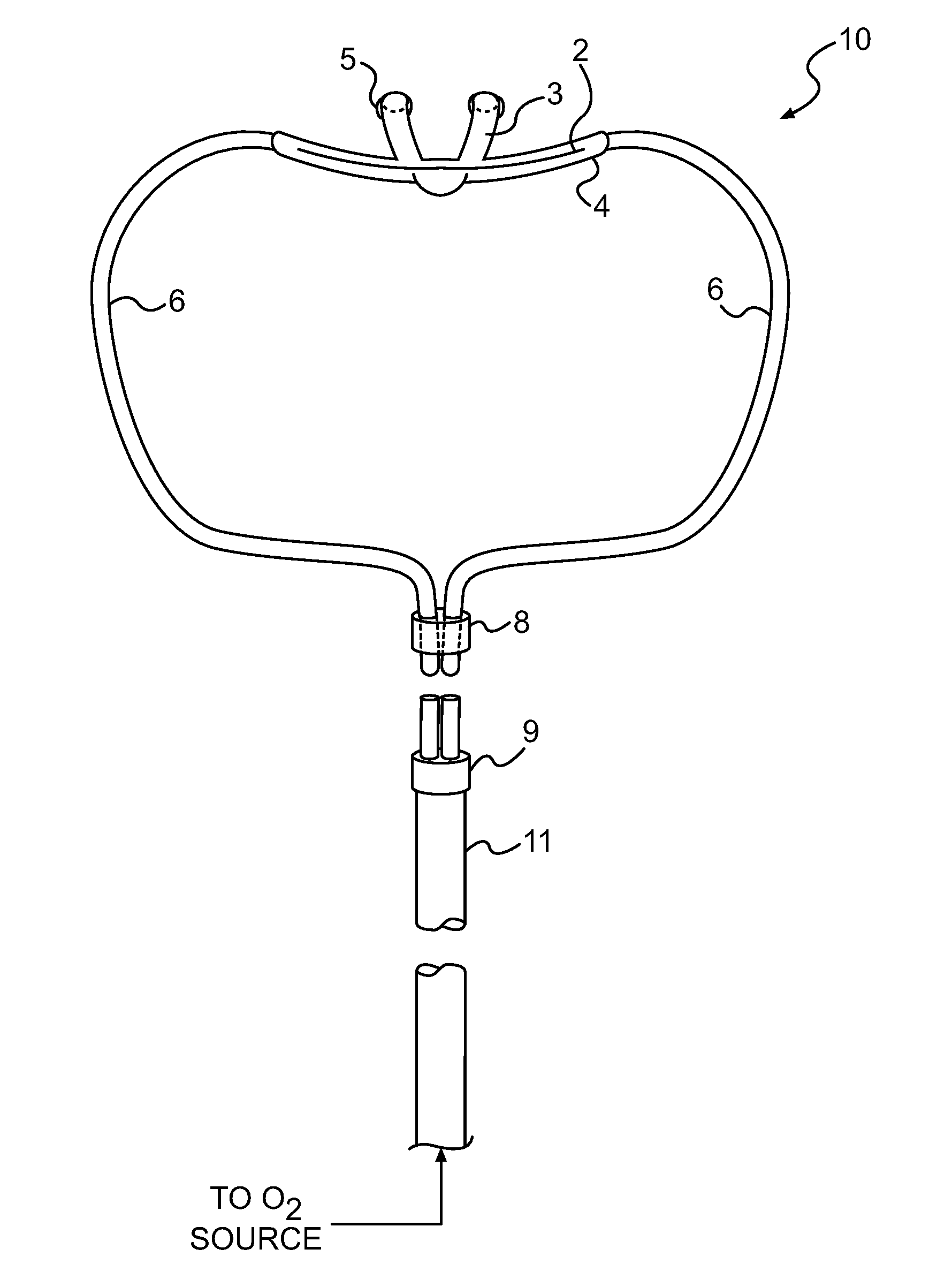
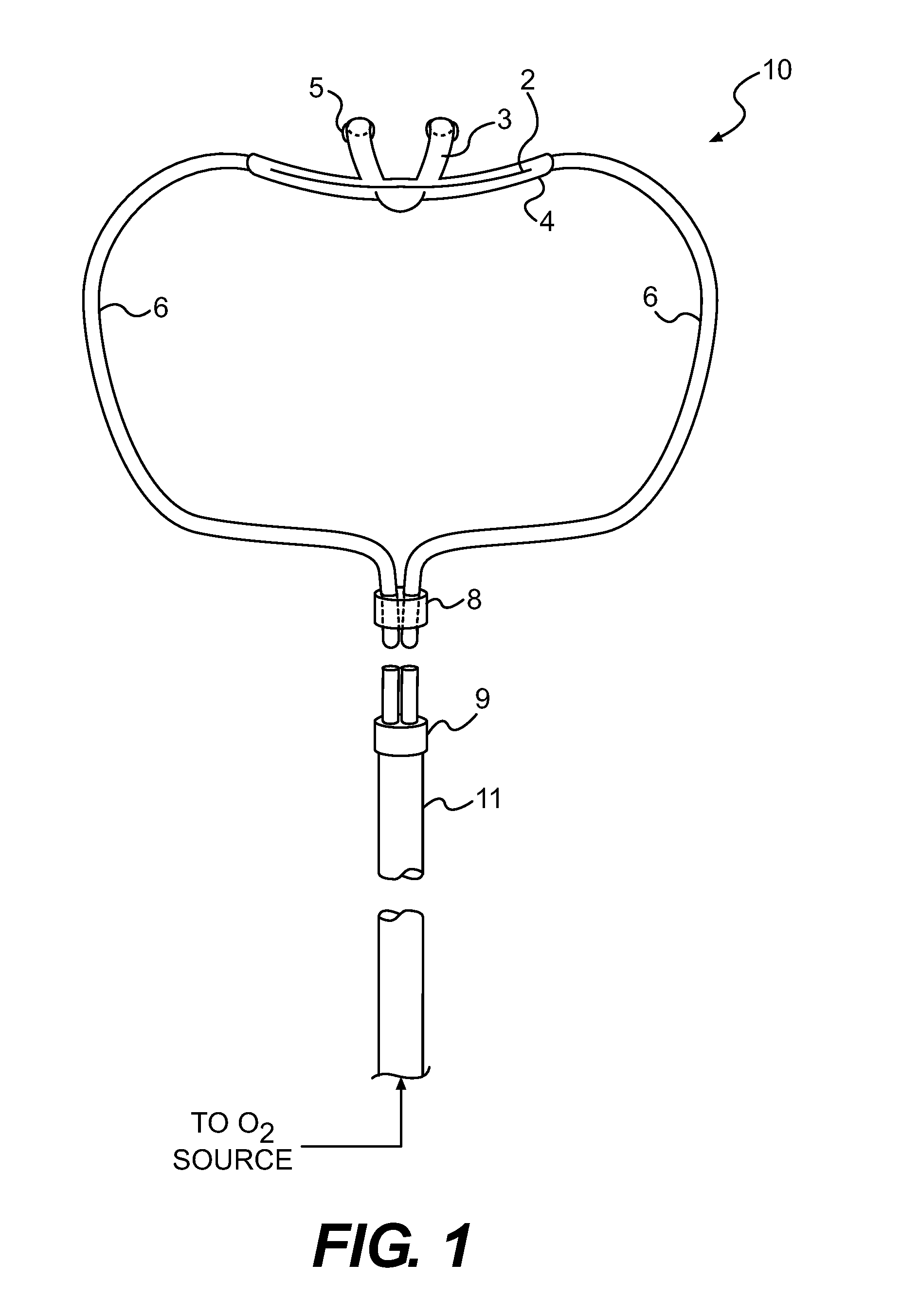
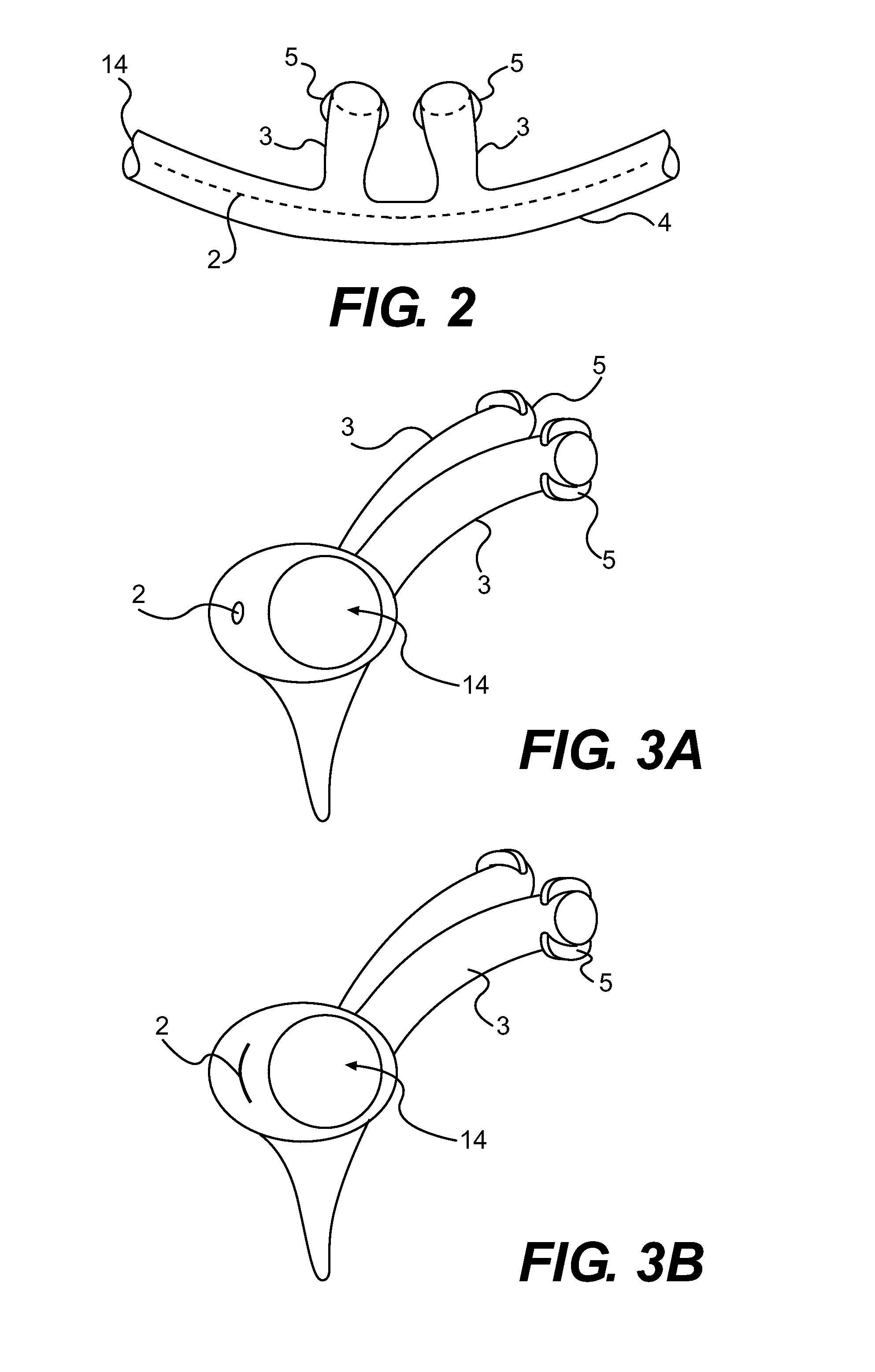
[0031]Reference will now be made in detail to embodiments of the present invention, examples of which are illustrated in the accompanying drawings. An embodiment of the present invention is a nasal cannula assembly designed to deliver continuous positive airway pressure (“CPAP”) to improve oxygenation during spontaneous ventilation in the operating, procedure room, or critical care area by sealing off the nostrils from outside air and by providing a mechanism to allow the nasal cannula to conform to the patient's facial anatomy to facilitate a complete seal. The device is designed to be easy and quick to apply, comfortable for the patient and relatively inexpensive.

[0032]In contrast to other nasal CPAP devices, embodiments of the present invention use unique approaches to seal the nostrils to create nasal CPAP to overcome upper airway obstruction while being easily and quickly applied to the patient.

[0033]Unlike other CPAP devices, an embodiment of the present invention comprises so...


PUM


Abstract

An embodiment of the present invention is a nasal cannula for delivering continuous positive airway pressure (“CPAP”) to a patient's nares during operative procedures or in critical care areas. A malleable metal or plastic is encased in the bridge of the cannula to allow it to be shaped to the patient's face. As a result of contouring the cannula to the face, air leaks are minimized allowing a seal to be provided when an op site is applied to cover the upper lip, nasal cannula and nose. The cannula's nasal inserts can end in nontapered or slightly tapered non-sealing beads, which may be slightly angled out to accommodate various facial anatomies. When approximately several liters per minute of oxygen are flowed through the cannula, CPAP is obtained.

Description

CROSS-REFERENCE TO RELATED APPLICATIONS[0001]The present invention relates to, and is entitled to the benefit of the earlier filing date and priority of, U.S. Application No. 61 / 157,440 filed on Mar. 4, 2009, which is herein incorporated by reference as if fully set forth.BACKGROUND OF THE INVENTION[0002]Continuous nasal positive airway pressure or continuous positive airway pressure (“CPAP”) has been used to treat a variety of diseases including sleep apnea. Most devices used to treat sleep apnea are expensive, cumbersome and designed for repeat use; therefore, they are not used in the operating room, emergency room, or critical care areas. During sedative anesthesia using nasal cannula to deliver oxygen, it is not uncommon for the patient's airway to obstruct as in sleep apnea and for the patient to become hypoxic. This is more marked during procedures in which the upper airway is shared with the surgeon or endoscopist. Various maneuvers such as delivering high oxygen flow rates o...

Claims


Application Information

Patent Timeline
Patent Type & Authority Applications(United States)
IPC IPC(8): A61M16/00
CPCA61M16/0666A61M16/0688A61M2202/0208A61M16/0683A61M2205/0266
Inventor JABLONS, MITCHELL L.
Owner JEMI AIRWAY MANAGEMENT
Why Eureka
Try Eureka