Eureka AIR delivers breakthrough ideas for toughest innovation challenges, trusted by R&D personnel around the world.

Methods and apparatus for lubricating suspension components

Active Publication Date: 2010-09-09
FOX FACTORY
View PDF10 Cites 19 Cited by
  • Summary
  • Abstract
  • Description
  • Claims
  • Application Information

AI Technical Summary

Problems solved by technology

Thus, the vehicle suspension undergoes a wide range of tough conditions that puts pressure on the functionality of its internal components.
What is needed are vehicle suspension assemblies that better accommodate these performance requirements, as there exists many limitations to the present state of vehicle suspension technology.

Method used


Image

  • Methods and apparatus for lubricating suspension components
  • Methods and apparatus for lubricating suspension components
  • Methods and apparatus for lubricating suspension components

Examples


Embodiment Construction

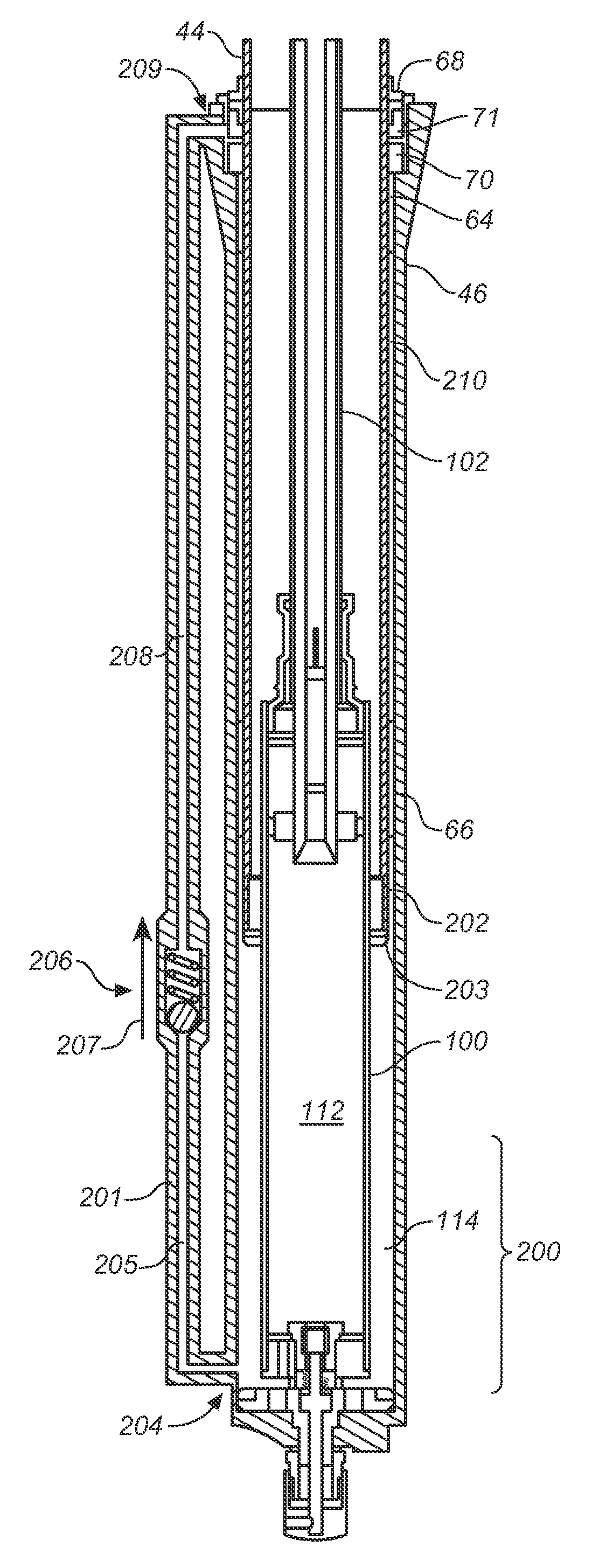
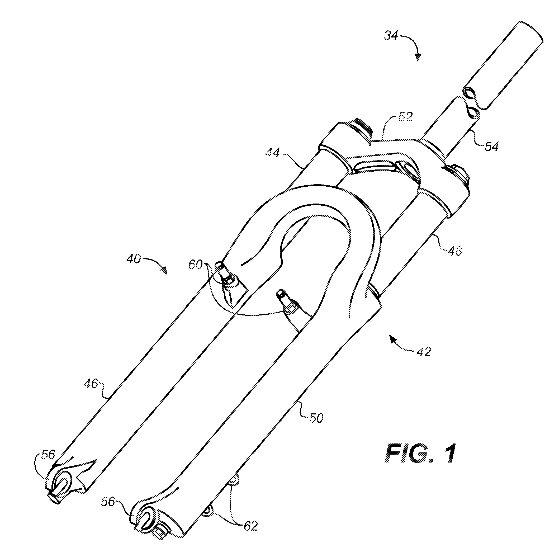
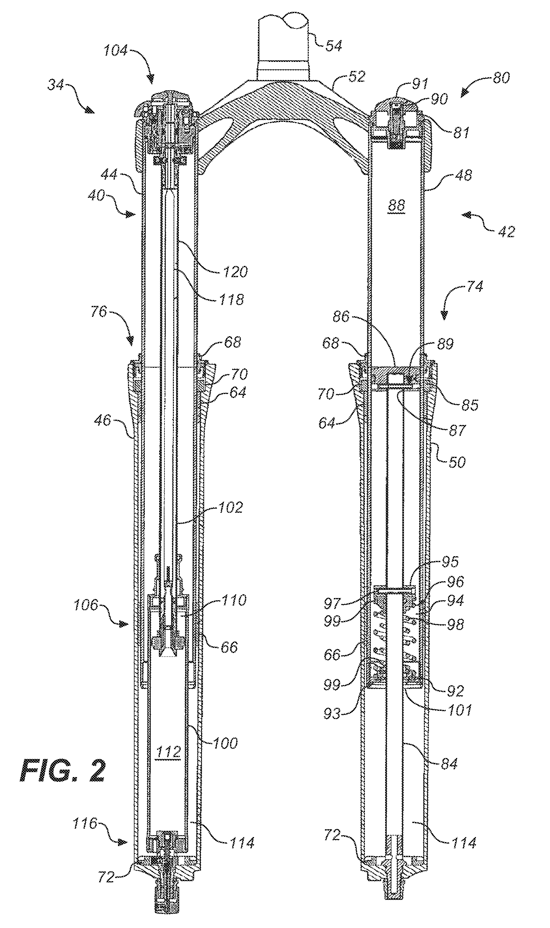
[0013]Vehicle wheel suspension often includes a damping mechanism for dissipating energy (e.g. from inertial wheel movement induced by disparities in the terrain over which the vehicle travels) and a spring mechanism for storing energy to rebound a compressed suspension to an uncompressed state. Damping assemblies often convert wheel movement into heat by means of fluid friction in a dashpot type device. Spring mechanisms may take many forms including, coiled springs, elastomer bumpers, compressible fluid (e.g. gas, silicone oil), suitable combinations thereof or other suitable energy storage mechanisms. Vehicles having a single front wheel, such as for example motorcycles and bicycles, often have front suspension assemblies in the form of a “fork” as shown in FIG. 1. The fork 34 shown in FIG. 1 includes lower leg tubes 46 and 50 having upper leg tubes 44 and 48 telescopically engaged respectively therewith. Crown 52 holds the telescopic fork legs in spaced relation to steering tube...


PUM


Abstract

Methods and apparatus for lubricating suspension seals by pumping fluid to the seals using a compression or rebound action of a suspension component.

Description

CROSS-REFERENCE TO RELATED APPLICATIONS[0001]This application claims priority to and benefit of U.S. provisional patent application 61 / 094,324 filed Sep. 4, 2008, which is incorporated herein, in its entirety, by reference.FIELD OF THE INVENTION[0002]Embodiments of the invention generally relate to methods and apparatus for use in suspension assemblies. Particular embodiments of the invention relate to methods and apparatus useful for lubricating components of telescopic vehicle suspension.BACKGROUND[0003]Vehicles, including wheeled vehicles, are typically suspended to absorb shock encountered while traversing uneven terrain. Fundamental vehicle suspensions for controlling vehicle body motion and handling characteristics during vehicle travel over uneven surface are well-known in the art. Wheeled vehicles usually include one vehicle suspension assembly per wheel so that each wheel may absorb shock independently. Vehicle suspensions typically comprise many components, including a hyd...

Claims


Application Information

Patent Timeline
IPC IPC(8): B60G15/00B60R17/02
CPCF16F9/3278B62K25/08F16N13/00F16F9/185F16F13/007F16F2230/04
Inventor GALASSO, MARIOHAUGEN, DAVID
Owner FOX FACTORY
Why Eureka
Eureka Blog
Learn More