Illuminated visor vanity

a technology of led lights and vanity mirrors, applied in sun visors, process and machine control, instruments, etc., can solve problems such as adversely affecting the illumination of led lights

Inactive Publication Date: 2010-09-09
INT AUTOMOTIVE COMPONENTS GRP NORTH AMERICA INC
View PDF54 Cites 8 Cited by
  • Summary
  • Abstract
  • Description
  • Claims
  • Application Information

AI Technical Summary

Problems solved by technology

During periods of cold weather, the voltage output from the battery may be between two

Method used


Image

  • Illuminated visor vanity
  • Illuminated visor vanity
  • Illuminated visor vanity

Examples


Embodiment Construction

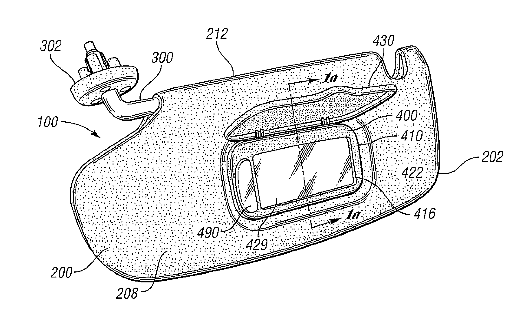
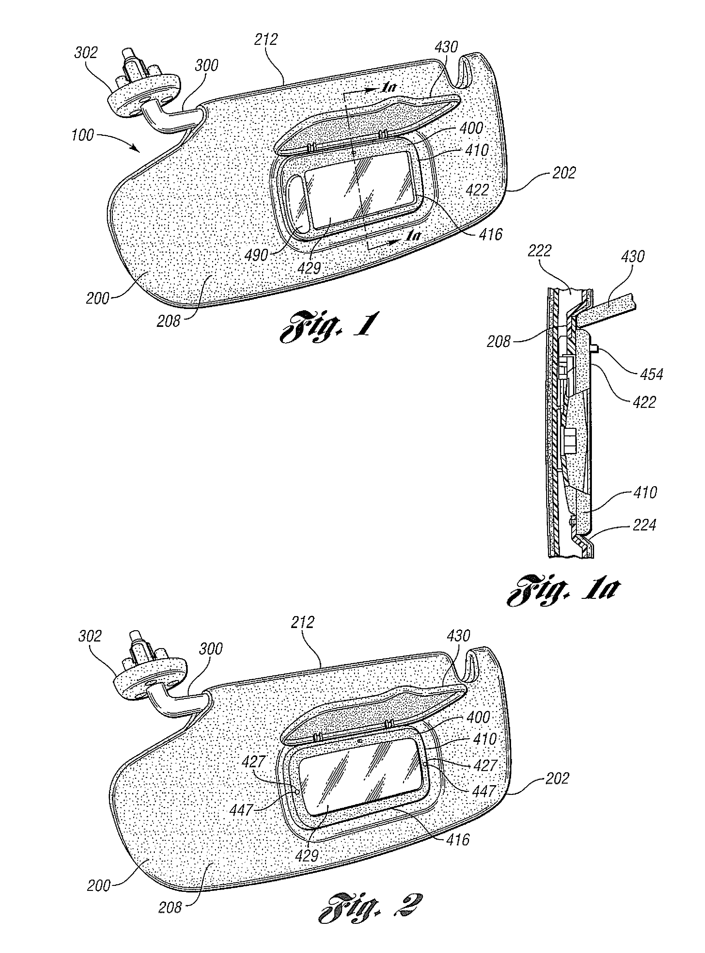
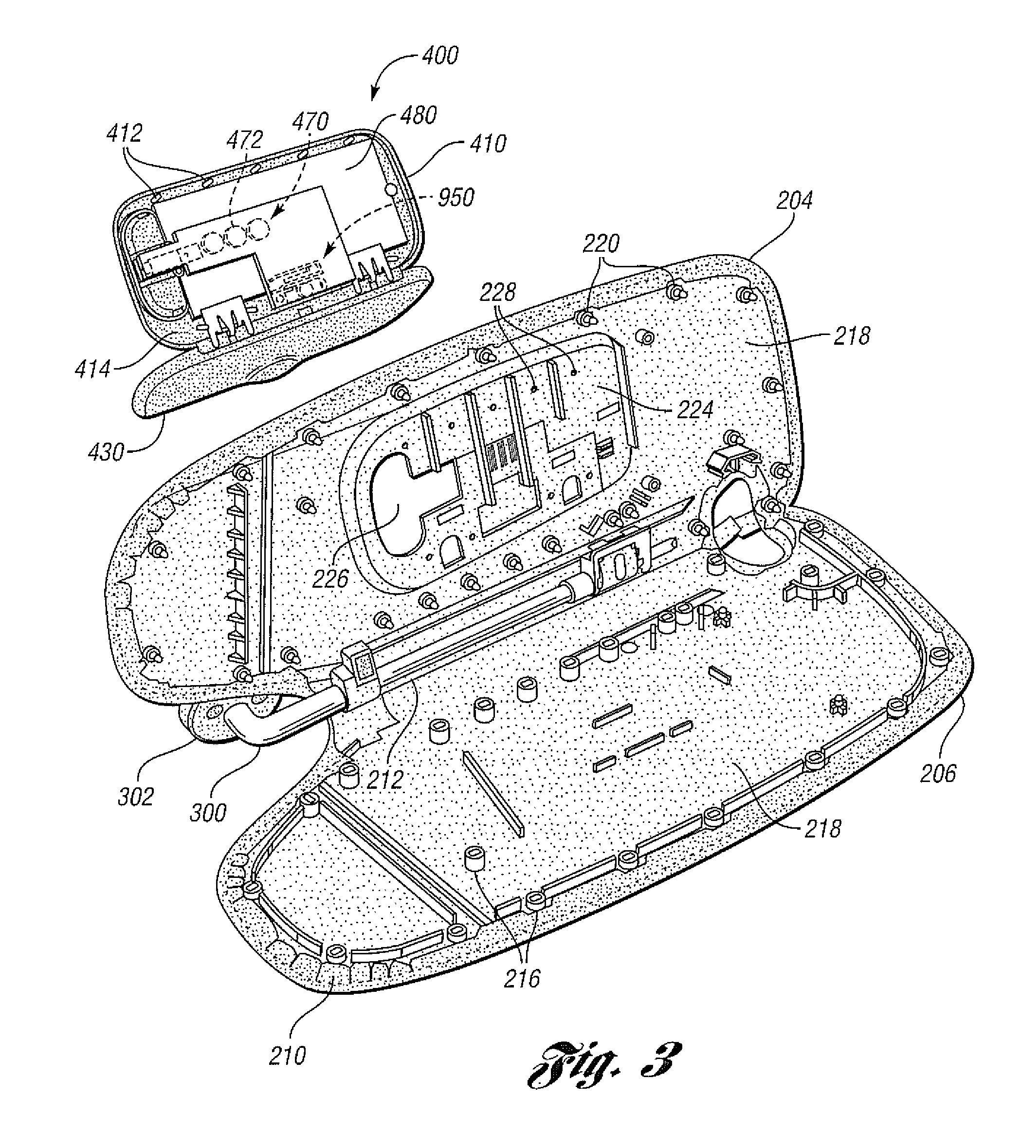
[0019]Referring to FIG. 1, a visor assembly 100 includes a visor 200 and a visor arm 300 having a visor bracket 302 of a conventional design.

[0020]The visor arm 300 is typically mounted to the visor bracket 302 which in turn may be mounted to any suitable mounting surface, such as the sheet metal of the vehicle roof (not shown). The visor arm 300 is typically pivotally connected to the visor bracket 302 such that the visor arm 300 together with the visor 200 may be moved into desired positions. For example, the visor arm 300 may typically be pivoted at the visor bracket 302 such that the visor 200 may be moved into positions such as adjacent to the front or side windows of a vehicle. Such brackets and pivotal connections are well known in the art and will not be described in further detail here.

[0021]The visor 200 is preferably mounted to the visor arm 300 via a torque control such that the visor 200 may be rotated relative to the visor arm 300. Such a torque control is preferably m...


PUM


Abstract

A visor vanity including a visor body for a vehicle having an electrical system is provided. The visor body includes a visor mirror, at least one light source, a switch, a regulator circuit and a timer. The switch causes at least one energy source that is independent of the electrical system of the vehicle to generate a first voltage signal. The regulator circuit is operably coupled to the switch and to the energy source for transmitting a second voltage signal in response to the first voltage signal so that the light source receives the second voltage signal. The timer is powered by the energy source for causing the regulator circuit to disable the operation of transmitting the second voltage signal in response to the timer achieving a predetermined count value.

Description

BACKGROUND[0001]1. Technical Field[0002]One or more embodiments of the present invention generally relate to a battery powered vanity mirror and light assembly having a regulator circuit therein for use in a vehicle.[0003]2. Background Art[0004]Lithium batteries are generally used for powering light emitting diodes (LEDs) in a power vanity lighting mirror. For example, such batteries may provide up to three volts to power the LEDs. The voltage may decrease to two volts the longer the battery is switched on. During periods of cold weather, the voltage output from the battery may be between two and three volts, such voltage levels may adversely affect the illumination of the LEDs.[0005]It is generally recognized that LEDs are powered with a voltage of between 2.8 and 3.6 volts. Such an input voltage requirement varies from LED to LED. The light intensity of the LEDs may vary based on the amount of voltage used to power the LEDs within the mirror.SUMMARY[0006]A visor vanity including a...

Claims


Application Information

Patent Timeline
IPC IPC(8): H05B37/02
CPCH05B33/0842Y02B20/42H05B37/0281H05B47/16Y02B20/40H05B45/345B60Q3/82B60Q3/252H05B45/375H05B45/38
Inventor CRUICKSHANK, WILLIAMHOBSON, JAMESREICHHART, DERIKNICOLA, KIRK
Owner INT AUTOMOTIVE COMPONENTS GRP NORTH AMERICA INC
Why Eureka
Try Eureka