Tethered airfoil methods and systems

a technology of airfoil and power generation, applied in the direction of positive displacement liquid engine, pump, machine/engine, etc., can solve the problems of increasing the amount of power consumed by pumps, consuming power for dwindling returns, and difficulty in re-pumping remaining oil, so as to reduce the energy required for pumping

Inactive Publication Date: 2010-09-16
WINDLIFT LLC
View PDF14 Cites 27 Cited by
  • Summary
  • Abstract
  • Description
  • Claims
  • Application Information

AI Technical Summary

Benefits of technology

The present invention offers two methods: one involves using a kite system attached to a device for generating energy to create electricity and pump water, while another method involves utilizing a buoyant tethered airfoil system to revive a struggling oil well by reducing the amount of energy needed to pump the oil. These techniques offer cost savings and improved efficiency when producing energy and managing oil reservoirs.

Problems solved by technology

The technical problem addressed in this patent text is how to increase the efficiency with which we produce oil and related products while reducing the amount of waste and expense associated with traditional methods. Additionally, the text discusses the importance of considering both energy return and machine efficiency when evaluating various options for energy generation and usage. New technology solutions are necessary to address these challenges and improve the overall economic viability of oil production in the U.S.

Method used


Image

  • Tethered airfoil methods and systems
  • Tethered airfoil methods and systems
  • Tethered airfoil methods and systems

Examples


Embodiment Construction

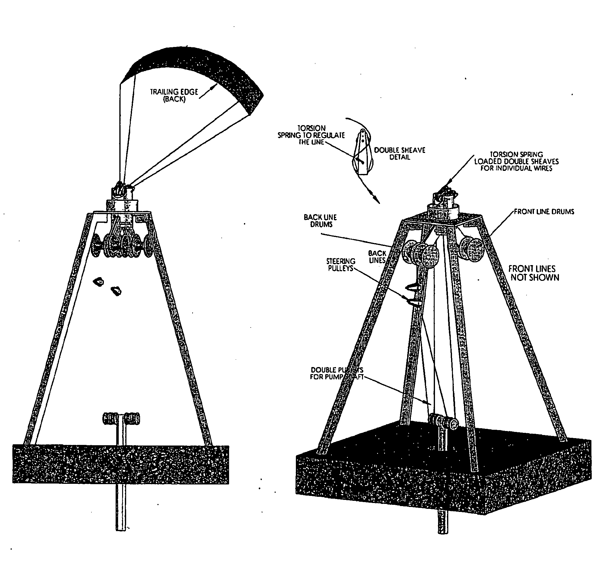
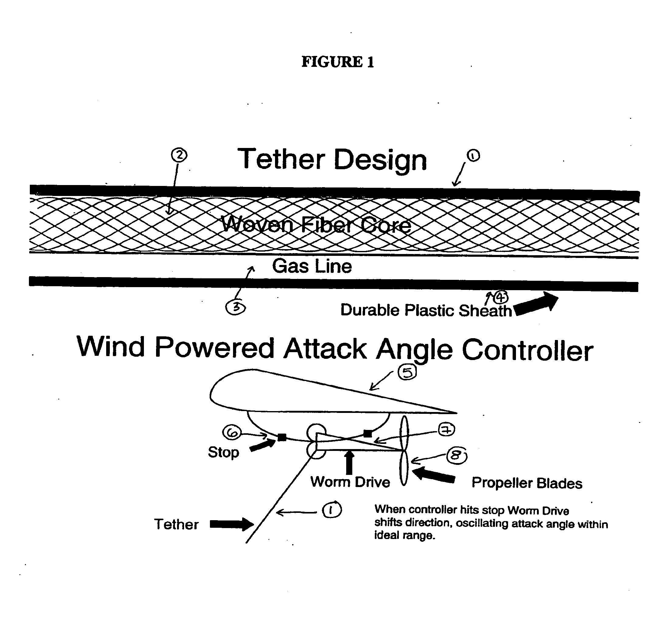
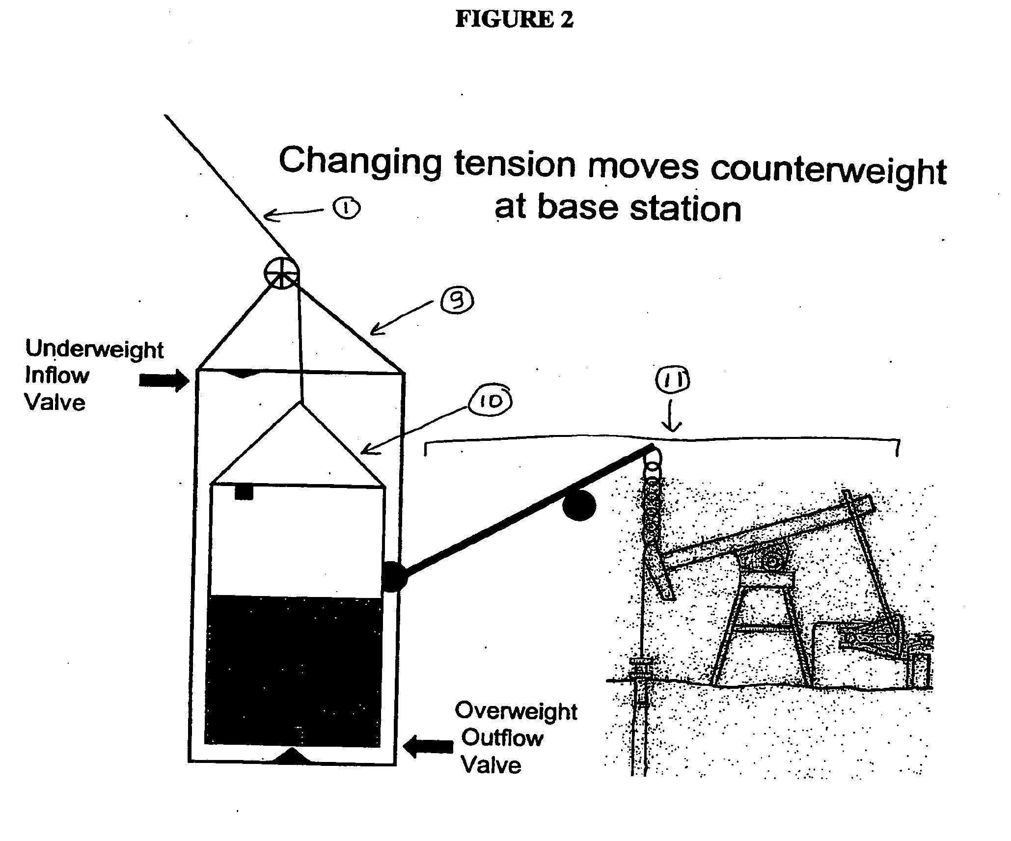
[0032]Certain embodiments of the present invention are described in more detail below. The present invention is not limited to these particular illustrative embodiments. Traditional oil pumping systems and energy generation systems require the use of a turbine, whereas the BTAG system is a direct drive system that does not require a turbine. An exemplary BTAG system of the invention is shown in FIGS. 1 and 2.

[0033]The following embodiments are not limited by the materials listed. Indeed, the materials listed are provided for exemplary purposes only, and those skilled in the art will recognize equally viable alternatives. Additionally, the airfoil is not limited by the dimensions of the airfoil, as all sizes of airfoils are contemplated. One skilled in the art would recognize size differences that would be optimal for varying conditions. FIG. 5 demonstrates different historical airfoil designs.

[0034]One embodiment of the present invention (FIGS. 1 and 2) comprises a lighter than air ...


PUM


Abstract

The present invention relates to methods and compositions for power generation using a tethered airfoil. In particular, the present invention provides a cost effective, environmentally friendly alternative to generate power for the oil, water, and electric industries or any other application where power is desired.

Description


Claims


Application Information

Patent Timeline
Owner WINDLIFT LLC
Why Eureka
Try Eureka