
Method and apparatus for compensation for skew in video signals

Active Publication Date: 2010-09-23
ATEN INT CO
View PDF22 Cites 7 Cited by
  • Summary
  • Abstract
  • Description
  • Claims
  • Application Information

AI Technical Summary

Benefits of technology

[0010]An object of the present invention is to perform skew detection an

Problems solved by technology

In the systems described above, skew testing and compen

Method used


Image

  • Method and apparatus for compensation for skew in video signals
  • Method and apparatus for compensation for skew in video signals
  • Method and apparatus for compensation for skew in video signals

Examples


Embodiment Construction

[0024]As required, a detailed illustrative embodiment of the present invention is disclosed herein. However, techniques, systems and operating structures in accordance with the present invention may be embodied in a wide variety of forms and modes, some of which may be quite different from those in the disclosed embodiment. Consequently, the specific structural and functional details disclosed herein are merely representative, yet in that regard, they are deemed to afford the best embodiment for purposes of disclosure and to provide a basis for the claims herein, which define the scope of the present invention. The following presents a detailed description of the preferred embodiment (as well as some alternative embodiments) of the present invention.

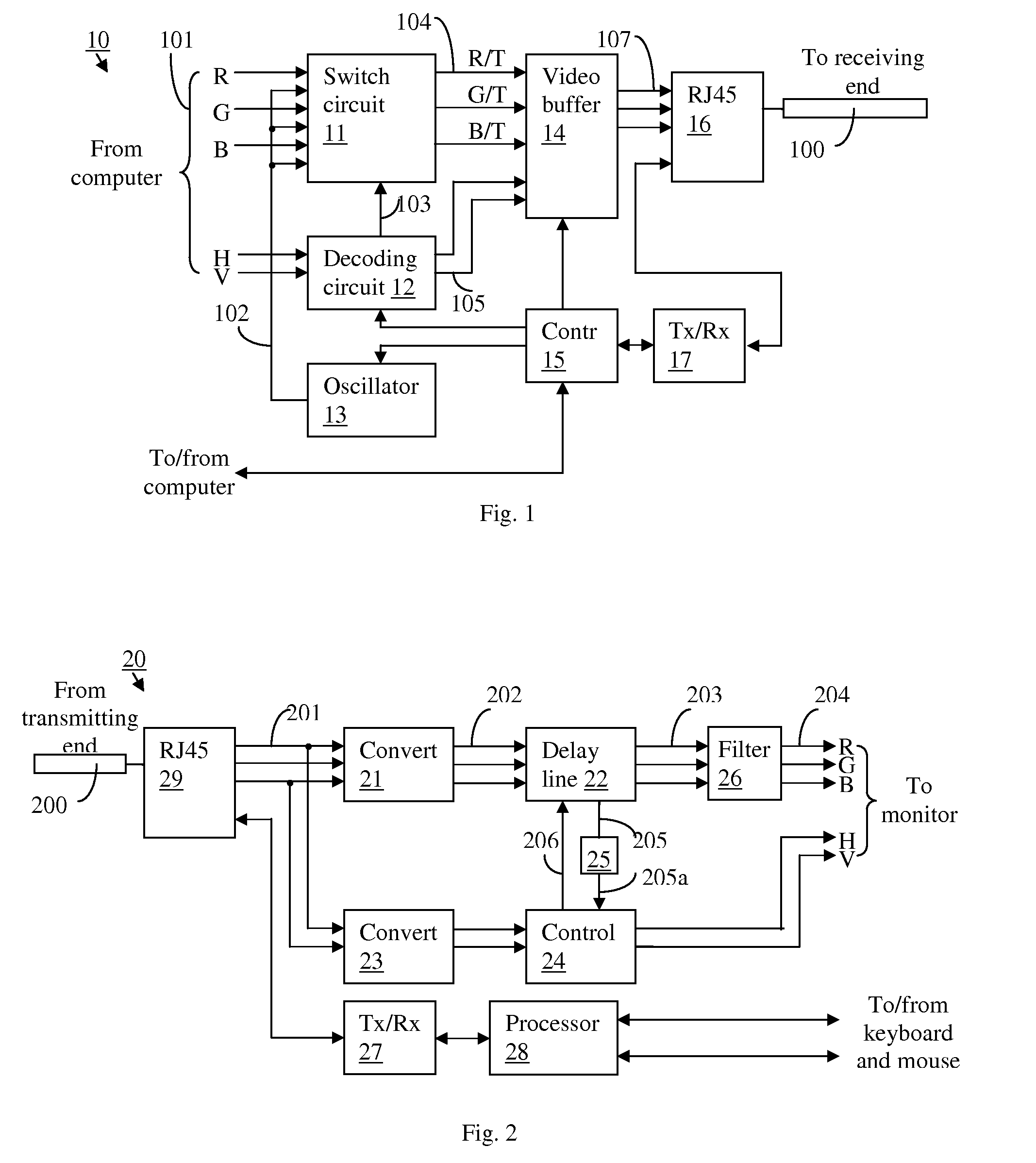
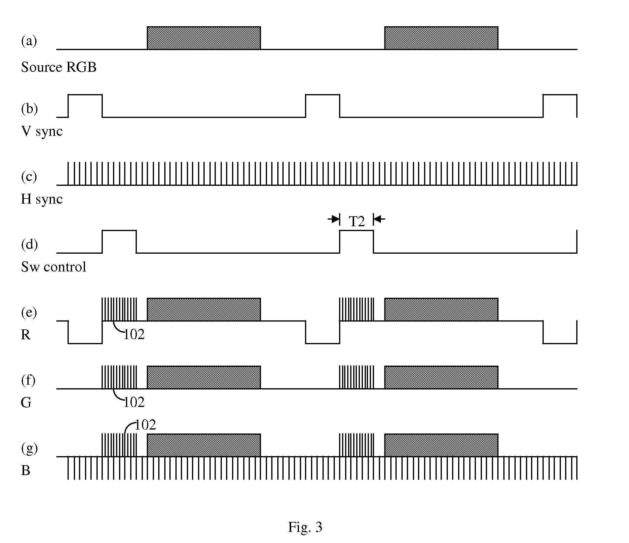
[0025]According to embodiments of the present invention, test signal and normal video signal are transmitted concurrently over the transmission cable. Test signals for skew detection and compensation are transmitted within predetermined ...


PUM


Abstract

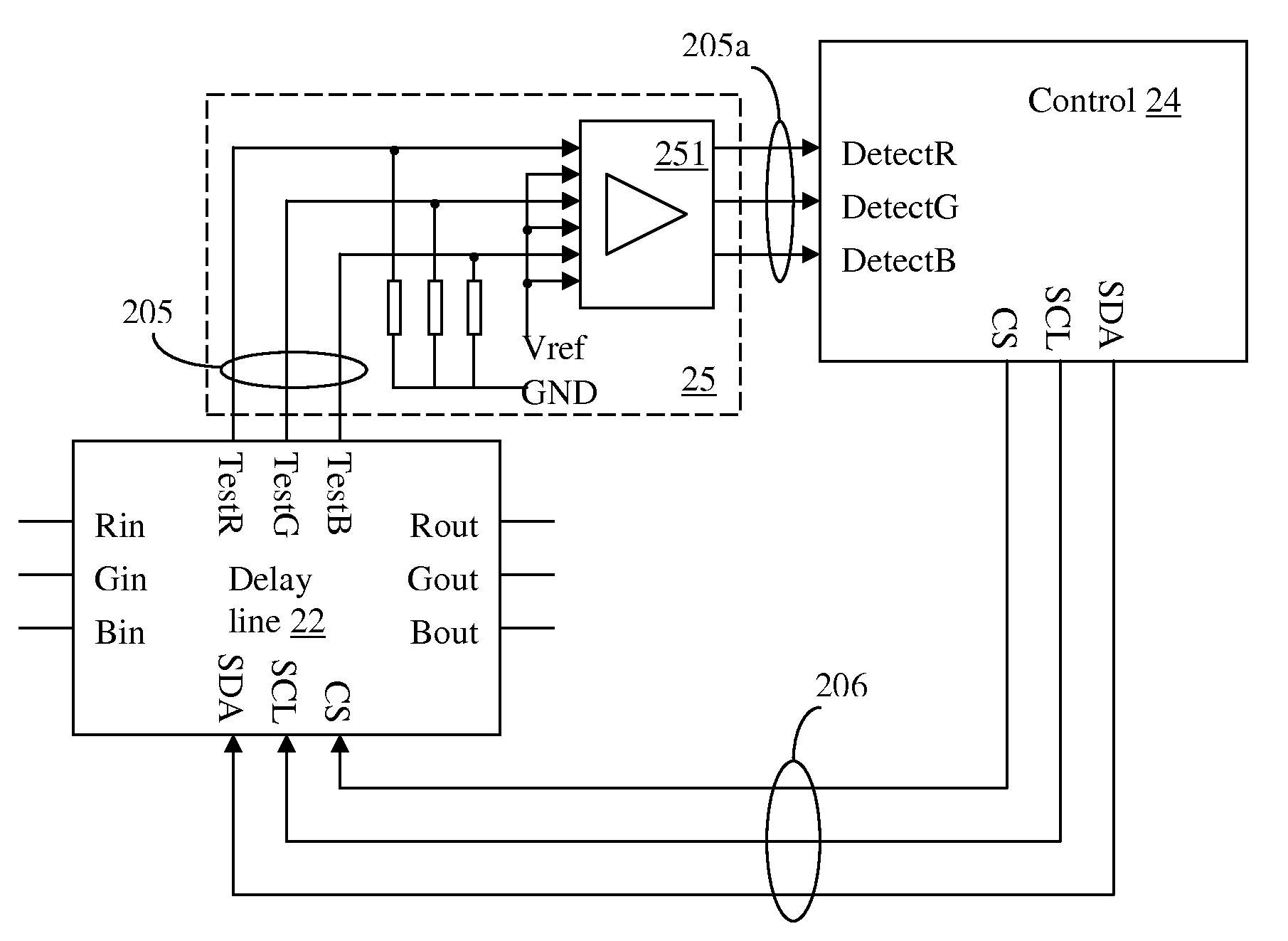
A system for compensating for skew in a color video signal transmitted by a cable having multiple conductors is described. A test pulse signal (e.g. a 2 MHz signal) is inserted into the color components (e.g. RGB) of the video signal during time periods in each frame when the RGB video signals are inactive, such as within 300 μs after the V sync signal. After transmission over the cable, the RGB components with the inserted test signal are delayed relative to each other using a delay line in cooperation with a control circuit. The delay line generates detect signals by detecting relative delays of the test signal pulses inserted in the RGB components. The control circuit controls the amount of delay in the delay line based on the detect signals, so that the RGB components in the video signal outputted by the delay line are synchronized.

Description

BACKGROUND OF THE INVENTION[0001]1. Field of the Invention[0002]This invention relates to video signal compensation, and in particular, it relates to circuitry and related methods for detecting and compensating for color separation in video signals transmitted over a cable with multiple transmission wires.[0003]2. Description of the Related Art[0004]In various systems, such as computer systems, where analog color video signals from a video source such as a computer is transmitted over relatively long transmission lines having multiple conductor lines such as a category 5 (Cat 5) cable, to a remote display device such as a monitor, the color components such as RG B components of the video signal often become slightly delayed relative to each other when they arrive at the display device. This is sometimes referred to as skew, and is typically caused by the slight length difference of the conductor wires in the cable that carry the different color components of the video signal. As a r...

Claims


Application Information

Patent Timeline
IPC IPC(8): H04N17/00H04N9/47G06F3/02
CPCG06F3/1454G09G5/008H04N17/00G09G2370/24H04N7/108G09G2320/0242
Inventor GOU, YUN-SONGWEN, HONG-TAOZHUANG, QIAN-QI
Owner ATEN INT CO
Learn More