
Eureka
For R&D, Eureka makes reading and utilizing patents & technical documents easy.
Eureka AIR
Designed for self-driven R&D workflows. Generate viable solutions, solve complex R&D challenges, empower your innovation with AI.

Eureka Materials
Designed for material experts only. Revolutionize your material R&D, from search, analyze, to developing new materials.

TechResearch
Generate reliable direction feasibility study reports for your R&D in just a few steps.

TechSeek
Discover and master advanced knowledge NOW. Basics, ideas, possibilities, all at once.

TechMind
As an expert in R&D Theories, TechMind can generates customized viable solutions instantly.

TechRisk
Analyze your overall solution with one click, know your potential R&D risks in advance.

TechMonitor
Get weekly tech updates, stay abreast of the latest tech innovations and key insights.
Surgical microscope drape lens for reducing glare
- Summary
- Abstract
- Description
- Claims
- Application Information
AI Technical Summary
Benefits of technology
Problems solved by technology
Method used
Image

Examples
Example
DETAILED DESCRIPTION OF THE DRAWINGS
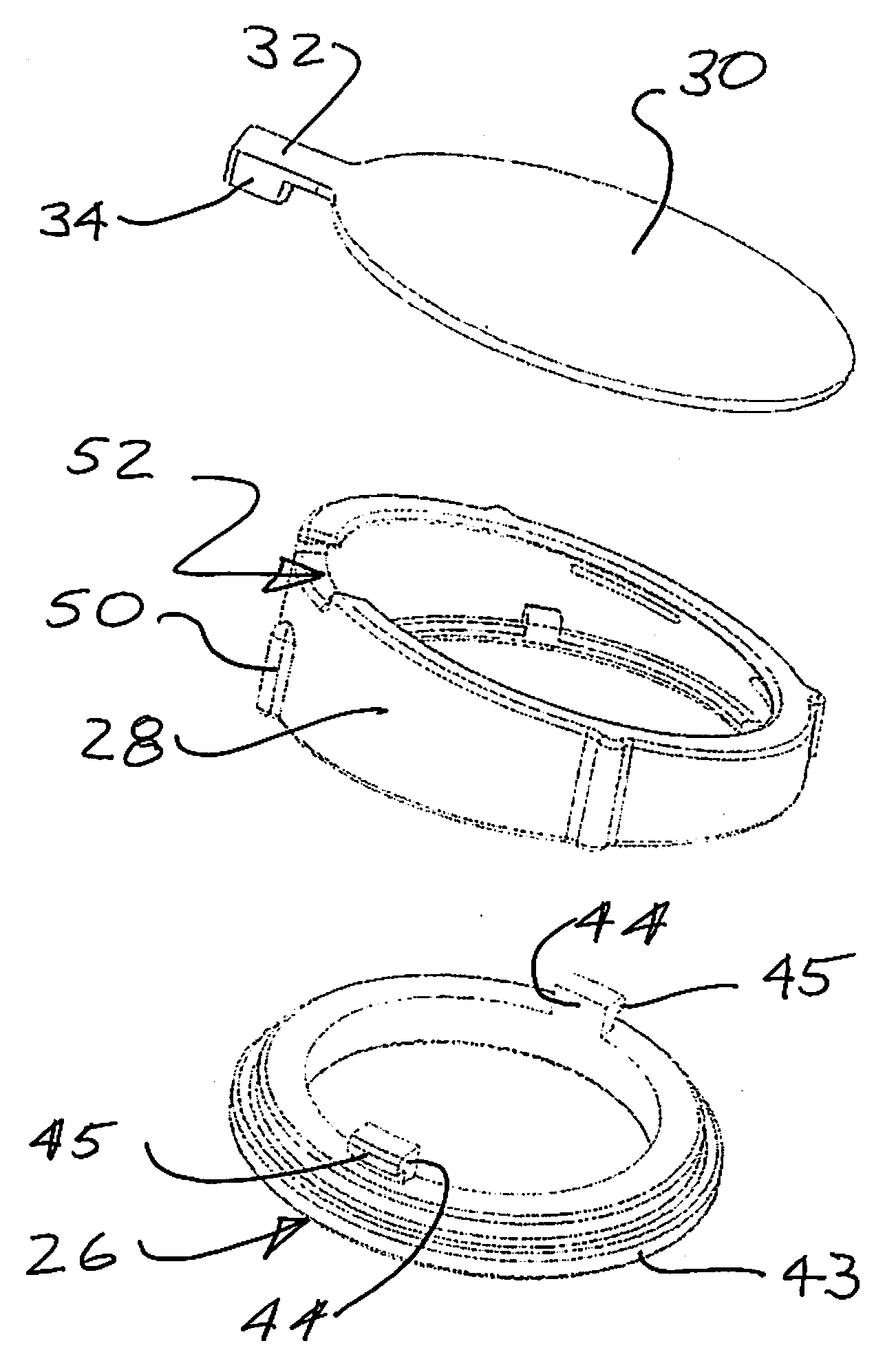
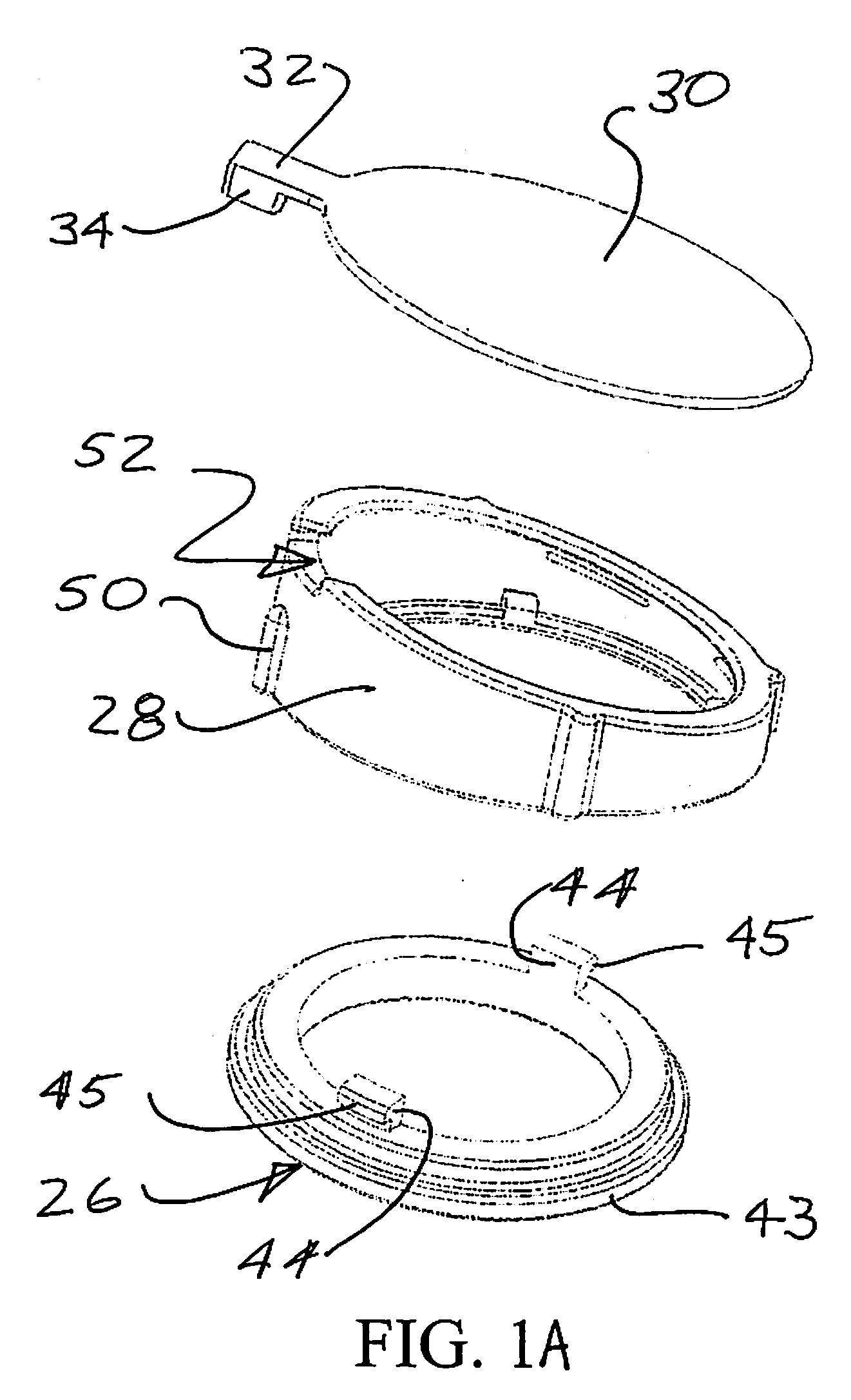
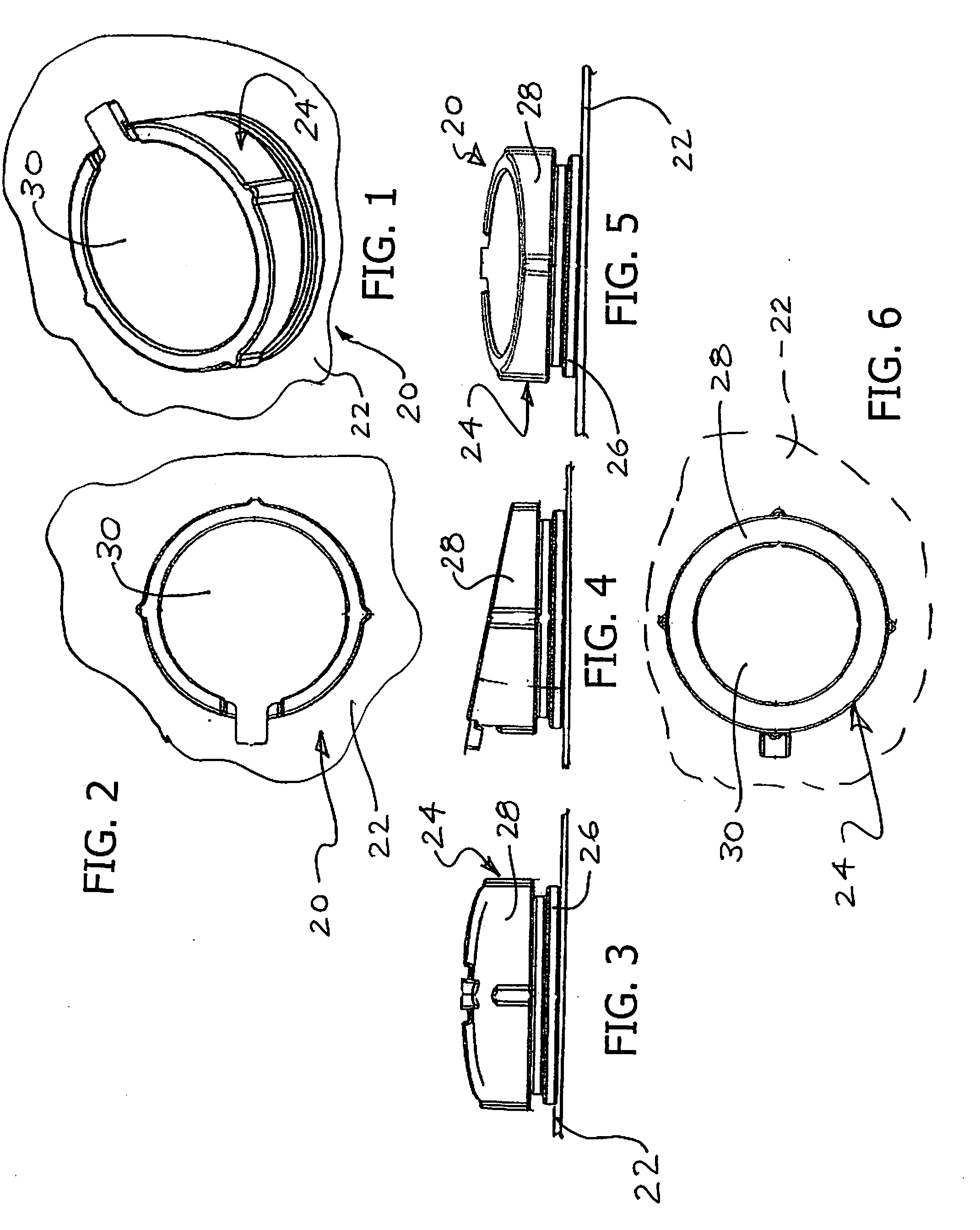
[0025]Turning now in detail to the drawings, as shown in FIGS. 1-6, a lens drape 20 includes a lens assembly 24 attached to a surgical drape 22. In the drawings, only the portion of the drape 22 surrounding the lens assembly 24 is shown. However, the drape 22 is dimensioned to cover a surgical microscope. The drape 22 may be a formed as tube or a bag. The lens assembly may have a diameter of e.g., about 8-15 cm. The size and shape of the drape 22 can vary depending on the type of microscope the lens drape 20 is to be used on.
[0026]The lens assembly 24 includes a drape ring 26, a lens ring 28 and a lens 30. These elements are shown assembled together in FIGS. 1-6. The drape ring 26 and the lens ring 28 are annular. The bottom surface 40 of the drape ring is attached to the drape 22, using adhesives, thermal bonding, or other generally permanent joining techniques. The drape material surrounded by the drape ring 26 is cut out and removed, leaving a ...
PUM
 Abstract
Description
Claims
Application Information
 - R&D Engineer
- R&D Manager
- IP Professional
- Industry Leading Data Capabilities
- Powerful AI technology
- Patent DNA Extraction
Browse by: Latest US Patents, China's latest patents, Technical Efficacy Thesaurus, Application Domain, Technology Topic, Popular Technical Reports.
© 2024 PatSnap. All rights reserved.Legal|Privacy policy|Modern Slavery Act Transparency Statement|Sitemap|About US| Contact US: help@patsnap.com