Tool for insertion and removal of in-canal hearing devices

a technology for in-canal hearing devices and tools, applied in the field of tools and methods for inserting and adjusting the position of hearing devices, can solve the problems of not understanding the variability of ear canals between individuals, and achieve the effects of limiting the medial advancement of tools, facilitating their insertion, and minimizing injurious conta

Active Publication Date: 2010-09-23
INSOUND MEDICAL INC
View PDF17 Cites 51 Cited by
  • Summary
  • Abstract
  • Description
  • Claims
  • Application Information

AI Technical Summary

Benefits of technology

[0013]The shaft may comprise a series of shaft portions which are detachable from one another. The length of the shaft may thereby be adjusted be attaching or detaching these shaft portions from each other. The shaft will typically be flexible to facilitate insertion into the tortuous ear canal and minimize injurious contact therein.
[0024]In many embodiments, the shaft is flexible to facilitate insertion into the tortuous ear canal and minimize injurious contact therein.
[0027]In another aspect, embodiments of the invention provide a tool for adjusting the positioning, for example, the medial-lateral and / or rotational positioning, of a hearing device placed within an ear canal of a user. The tool comprises a tube, a loop, a shaft, and a rest. The tube has a proximal end, a distal end adapted to capture the hearing device, and a side aperture having an adjustable length. The loop is for receiving a finger of a user and is coupled to the proximal end of the tube. The shaft is axially moveable and disposed within the tube. A distal portion of the shaft is adapted to abut the hearing device when the hearing device is captured by the distal end of the tube. The rest is for resting against a cheek of a user. The rest is coupled to a proximal portion of the first shaft and extends radially out of the side aperture of the tube. A portion of the rest is laterally abutted by an edge of the portion of the tube defining the side aperture. Pulling the tube in a lateral direction relative to the shaft causes the distal end of the tube to release the hearing device. Adjusting the length of the side aperture adjusts the axial position of the rest and the shaft within the tube.
[0029]In many embodiments, the shaft and the tube are flexible to facilitate insertion of the tool into the tortuous ear canal and minimize injurious contact therein.
[0032]In many embodiments, the distal portion comprises a side extension adapted to adapted to engage a wall of a conchal bowl of an ear of the user. The side extension limits medial advancement of the tool. The side extension may be shaped to conform to the conchal bowl. The distal portion may be flexible to facilitate its insertion into the tortuous ear canal and minimize injurious contact therein.
[0033]In another aspect, embodiments of the invention provide a tool for adjusting the positioning, for example, the medial-lateral and / or rotational positioning, of a hearing device placed within an ear canal of a user. The system comprises a rod and a mold. The rod has a proximal portion for handling by the user, a distal portion, and a distal end adapted to capture the hearing device. The mold is coupled to the distal portion of the rod. The mold is adapted to limit medial advancement of the rod into the ear canal. The mold may also be shaped to conform to a conchal bowl of an ear of the user. At least a distal portion of the rod may be flexible to facilitate insertion of the tool into the tortuous ear canal and minimize injurious contact therein.

Problems solved by technology

The aforementioned application in the name of Robert Schindler, however, does not appreciate the variability of the ear canal between individuals.

Method used


Image

  • Tool for insertion and removal of in-canal hearing devices
  • Tool for insertion and removal of in-canal hearing devices
  • Tool for insertion and removal of in-canal hearing devices

Examples


Embodiment Construction

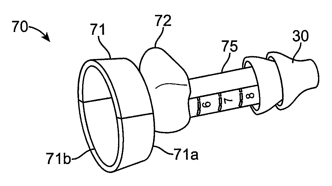
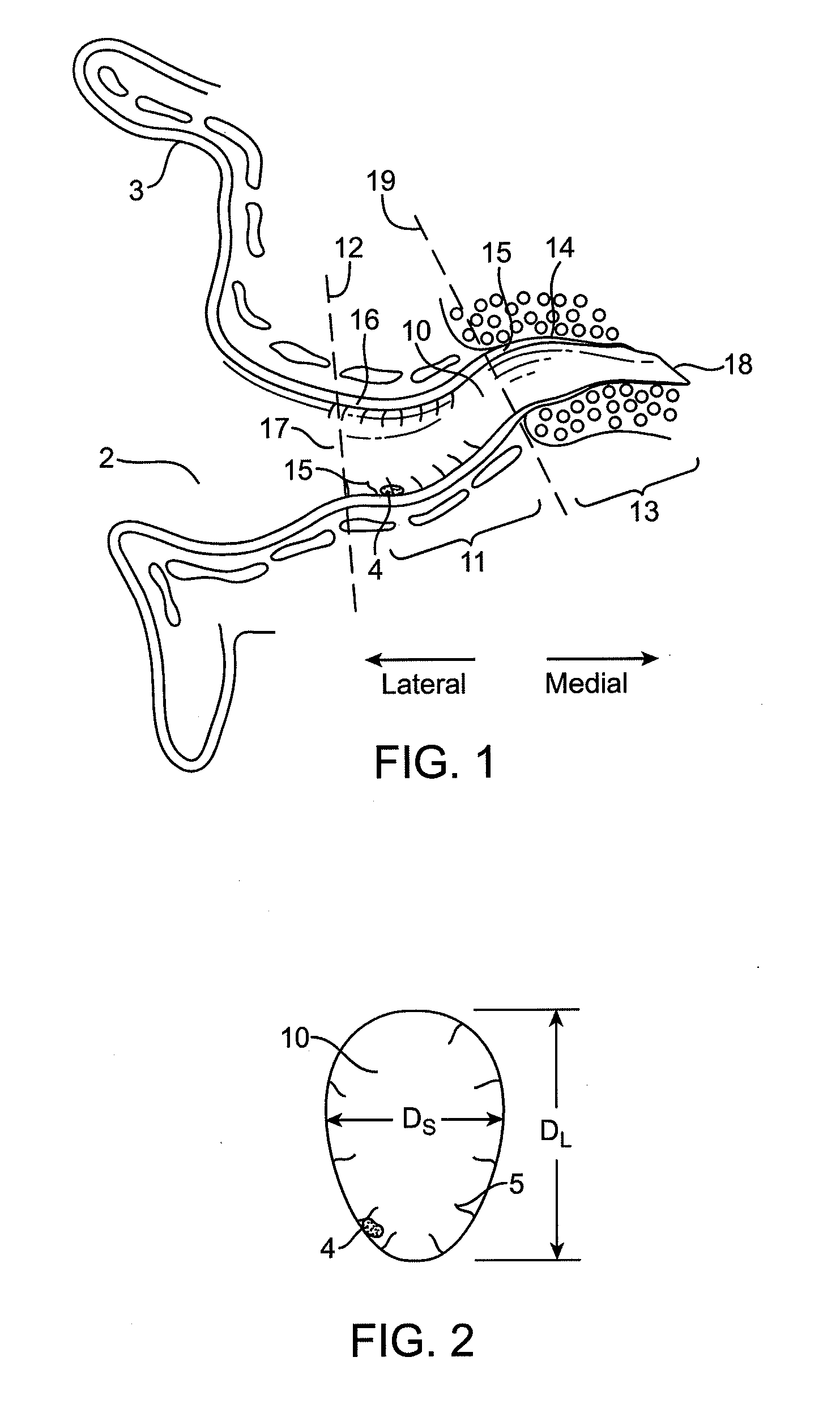
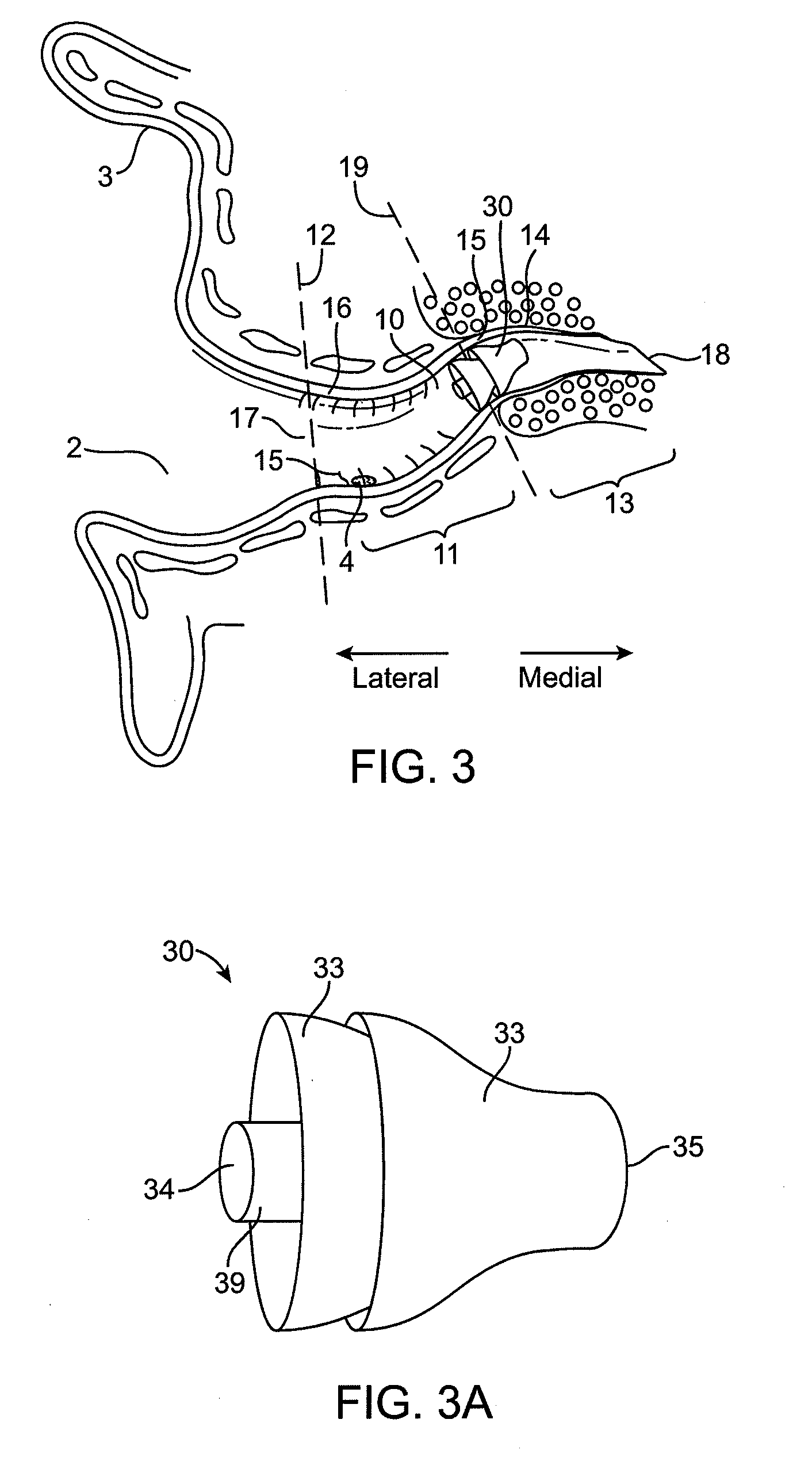
[0052]Referring now to FIG. 3, a side coronal view of the ear canal 10 with an in-canal hearing device 30 is shown. In-canal hearing device 30 will typically be designed to be positioned within the ear canal 10 at about the characteristic bend 15 at the bony junction 19.

[0053]FIG. 3A shows a side view of in-canal hearing device 30. In-canal hearing device 30 may comprise seals 33, a lateral end 34, and a medial end 36. The lateral end 34 comprises a lateral knob 39.

[0054]Embodiments of the invention typically provide tools and methods for adjusting the position of hearing devices worn in the ear canal. Under the supervision of a professional, the hearing aid 30 may be placed at an optimum position and / or orientation within the ear canal, e.g., at the bony junction 19. In at least some instances, the hearing device 30 may deviate from the position and / or orientation or may require removal, for example, using the tools described in co-assigned U.S. Pat. Nos. 7,388,961 and D509,054. Th...


PUM

PropertyMeasurementUnit
lengthaaaaaaaaaa
lengthaaaaaaaaaa
flexibleaaaaaaaaaa

Abstract

Methods, tools, and methods of manufacturing said tools are provided for inserting a hearing device deeply into the ear canal of a user and adjusting its medial-lateral position therein. The provided tools comprise a shaft. A distal end of the shaft can be coupled to the hearing device. The shaft is flexible to facilitate its insertion into the tortuous ear canal and minimize injurious contact with the ear canal. The length of the shaft can be adjusted to adjust the depth of insertion of the shaft into the ear canal, customizing the tool for an individual user. Medial advancement of the shaft into the ear canal is limited by a base, side extension, or mold coupled to a proximal portion of the shaft or other proximal part of the tool.

Description

BACKGROUND OF THE INVENTION[0001]1. Field of the Invention[0002]Embodiments of the present invention relate to tools and methods for inserting, adjusting the position of hearing devices worn in the ear canal, particularly the medial-lateral position of hearing devices worn deep in the ear canal, and removing devices.[0003]Since embodiments of the invention relate to adjusting the position of a hearing device from the ear canal, a brief description of the anatomy of the ear canal will now be presented for purposes of illustration. While the shape and structure, or morphology, of the ear canal can vary from person to person, certain characteristics are common to all individuals. Referring now to FIGS. 1-2, the external acoustic meatus (ear canal) is generally narrow and contoured as shown in the coronal view in FIG. 1. The ear canal 10 is approximately 25 mm in length from the canal aperture 17 to the center of the tympanic membrane 18 (eardrum), although the length of the ear canal c...

Claims


Application Information

Patent Timeline
Patent Type & Authority Applications(United States)
IPC IPC(8): H04R25/00
CPCH04R2460/17H04R25/608H04R25/00Y10T29/49771H04R25/603
Inventor HOWARD, ROBERTCHAUBERT, EVELYNEANDERSON, GRETCHENDOWNING, JONATHAN PAULHAUSMAN, NICHOLASHWU, JANET KARENPENATE, RICARDO
Owner INSOUND MEDICAL INC
Why Eureka
Try Eureka