Method of operating a compression ignition engine

Active Publication Date: 2010-09-30
J C BAMFORD EXCAVATORS LTD
View PDF7 Cites 2 Cited by
  • Summary
  • Abstract
  • Description
  • Claims
  • Application Information

AI Technical Summary

Benefits of technology

[0021]The invention has particular applicability where the engine is used to drive a generator, when the engine will normally be operated at a generally constant load (speed). Thus the en

Problems solved by technology

Although the pressure actually in the or one of the combustion chambers may be sensed,

Method used


Image

  • Method of operating a compression ignition engine
  • Method of operating a compression ignition engine
  • Method of operating a compression ignition engine

Examples


Example

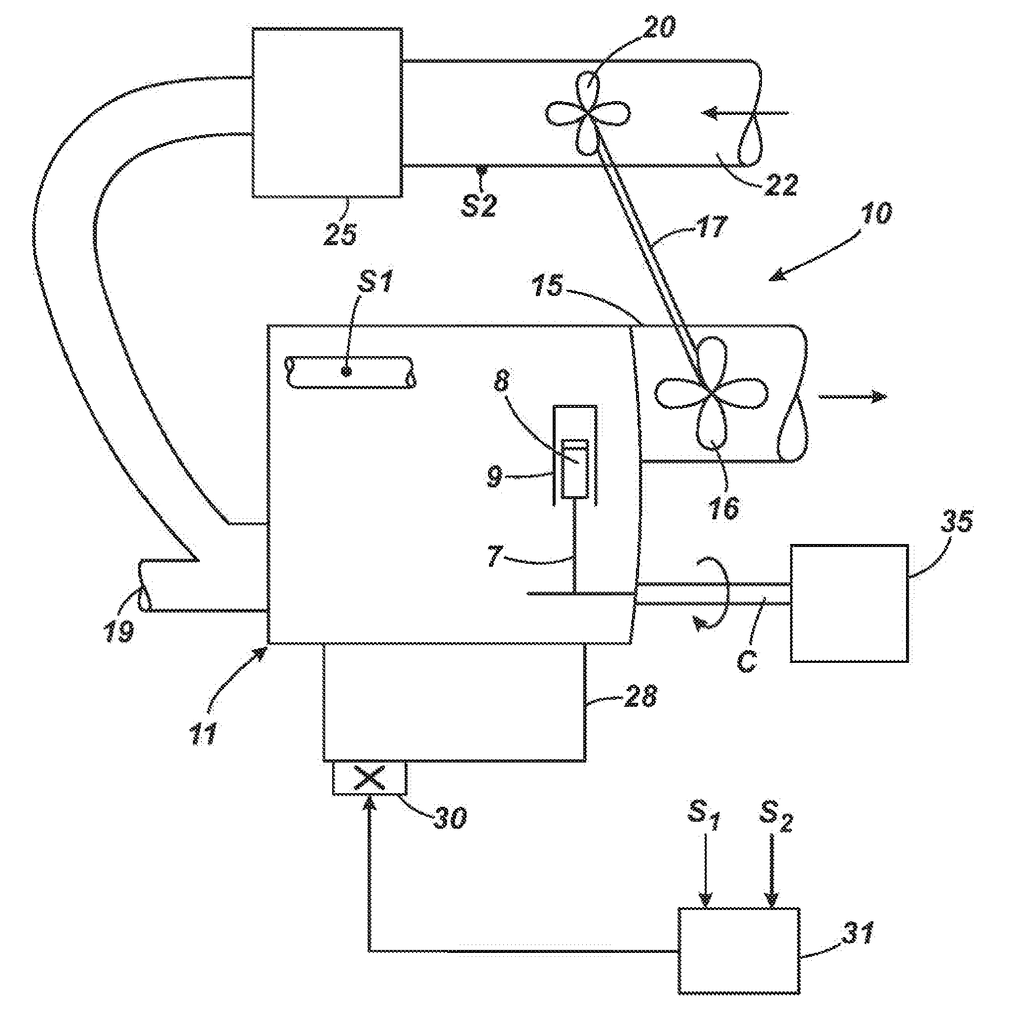
[0027]Referring to FIG. 1 a compression ignition engine 10 includes an engine block assembly 11 including a crank case (not shown) which houses a crankshaft C, a plurality of combustion chambers (four in the example—one of which is shown diagrammatically at 9) which each have a piston (one of which is shown at 8) reciprocal therein, the pistons 8 being connected to crankshaft C via connecting rods 7.

[0028]In use, fuel is injected either directly into each combustion chamber, or indirectly into a respective charge air airstream leading to the or a respective combustion chamber.

[0029]The engine 10 in the example is turbocharged, i.e. exhaust gases fed to a manifold 15 act on a turbine 16 to turn the turbine 16, and hence a shaft 17 on which the turbine 16 is provided, before the exhausted gases are exhausted. Some of the exhaust gases may be fed back to an air intake 19 for introduction back into the combustion chambers with charge air.

[0030]Mounted on the shaft 17 is a compressor 20 ...


PUM


Abstract

A method of operating a compression ignition engine, which includes at least one combustion chamber containing a piston, and a mechanically operated fuel injection pump apparatus. The method includes sensing the engine operating temperature with a first sensor, and providing input to a controller. The controller operates the fuel injection pump apparatus to deliver fuel to each of the combustion chambers according to a first timing regime when the engine operating temperature is above a threshold temperature, and according to a second, advanced timing, regime when the engine operating temperature is below the threshold temperature. The method further includes sensing the pressure in the combustion chambers with a second sensor. When the controller is operating the fuel injection pump apparatus according to the second timing regime and the combustion chamber pressure exceeds a desired pressure, the method includes changing operation from the second timing regime to the first timing regime.

Description

CROSS-REFERENCE TO RELATED APPLICATIONS[0001]This application claims priority under 35 USC 119(a)-(d) to United Kingdom Patent Application No. GB 0905049.3 filed on Mar. 25, 2009, which is incorporated by reference in its entirety herein.BACKGROUND TO THE INVENTION[0002]This invention relates to a method of operating a compression ignition engine such as a diesel engine, and more particularly to a method of operating a compression ignition engine in which fuel is delivered to the or each combustion chamber of the engine by a mechanically operated fuel injection pump apparatus.[0003]A mechanically operated fuel injection pump apparatus is typically driven by the engine, e.g. by the engine crankshaft, and includes one or more pumping chambers from which fuel is distributed for feeding directly into the or each combustion chamber by a or a respective injector, or indirectly, into a or a respective charge air airway or manifold, by an injector so that the fuel is mixed with the air in t...

Claims


Application Information

Patent Timeline
IPC IPC(8): F02D41/00H02P9/04
CPCF02D35/023F02D41/064F02D41/1448F02D29/06F02D2200/0406Y02T10/44F02D41/401Y02T10/40F02D1/025F02D41/3076F02D41/40
Inventor WOMERSLEY, ROBERT
Owner J C BAMFORD EXCAVATORS LTD
Why Eureka
Try Eureka