Power delivery system and method

a technology of power delivery system and power storage device, which is applied in the direction of electrochemical generator, fuel cell, and electrochemical stream management, can solve the problems of significant increase in the cost achieve the effects of increasing the output capacity of electrical energy storage device, increasing the electrical potential, and increasing the propensity

Active Publication Date: 2021-02-23
ESS TECHNOLOGY
View PDF9 Cites 1 Cited by
  • Summary
  • Abstract
  • Description
  • Claims
  • Application Information

AI Technical Summary

Benefits of technology

[0002]An electrical energy storage device may store electrical power that has been generated via an array of photovoltaic cells, wind turbines, hydroelectric generators, or other sources so that the electrical power may be delivered to electrical loads at a later time when output of the electrical power source may be low or when electrical loads are high. The electrical energy storage device may be comprised of a plurality of cells that may be coupled in series to increase the electrical potential of the electrical energy storage device. The electrical energy storage device may also include cells that are electrical coupled in parallel to increase the output capacity of the electrical energy storage device. As electrical potential of an electrical energy storage device increases, there may be a higher propensity for the electrical energy storage device to seek a lower electrical potential (e.g., earth ground) and discharge to the lower electrical potential. The possibility of discharging the electrical energy storage device to an object that is at a lower electrical potential may be reduced via increasing electrical insulation around and within the electrical energy storage device, but increasing the quantity and quality of the electrical insulation material may significantly increase cost of the electrical energy storage device. Therefore, it may be desirable to provide a way of reducing a possibility of unintentionally discharging an electric energy storage device to an object at lower electrical potential without substantially increasing cost of the electric energy storage device.
[0004]By electrically coupling the first electrolyte and the second electrolyte to an earth ground reference, it may be possible to bias positive and negative terminals of an electric energy storage device with respect to earth ground so that a possibility of discharging the electric energy storage device to earth ground or an object that is near earth ground may be reduced. In particular, a voltage of an electrolyte distribution manifold may be referenced to earth ground so that a voltage between a positive terminal and earth ground may be significantly reduced as compared to if a negative terminal of an electric energy storage device were referenced to earth ground. Consequently, it may be possible to provide a desired level of discharge protection for an electric power system via reduced insulating material.
[0005]The present description may provide several advantages. In particular, the approach may reduce power system cost. Further, the approach may be applied in a variety of ways that allow for a flexible system. In addition, the approach may reduce system weight and improve system reliability.

Problems solved by technology

The possibility of discharging the electrical energy storage device to an object that is at a lower electrical potential may be reduced via increasing electrical insulation around and within the electrical energy storage device, but increasing the quantity and quality of the electrical insulation material may significantly increase cost of the electrical energy storage device.

Method used


Image

  • Power delivery system and method
  • Power delivery system and method
  • Power delivery system and method

Examples


Embodiment Construction

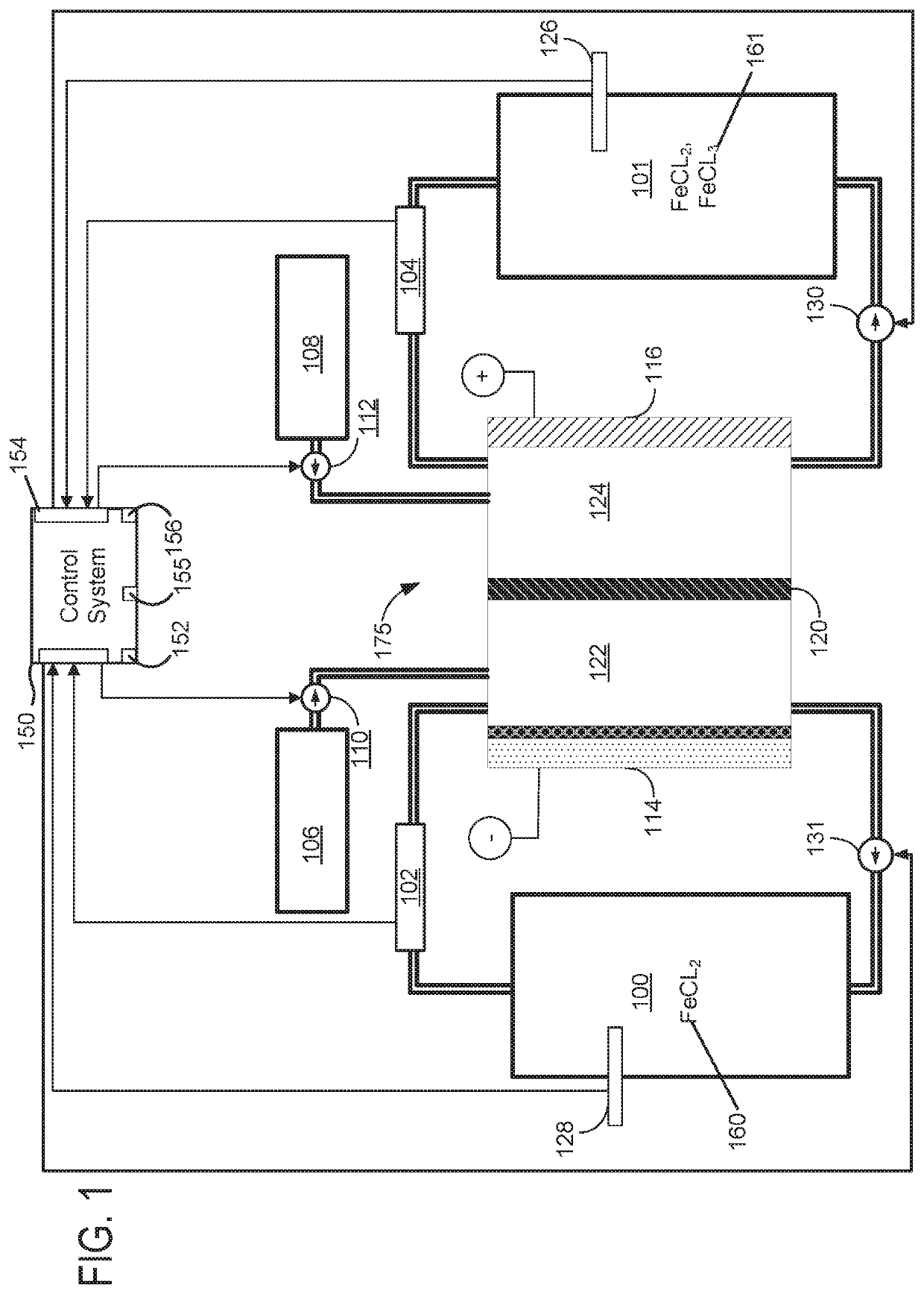
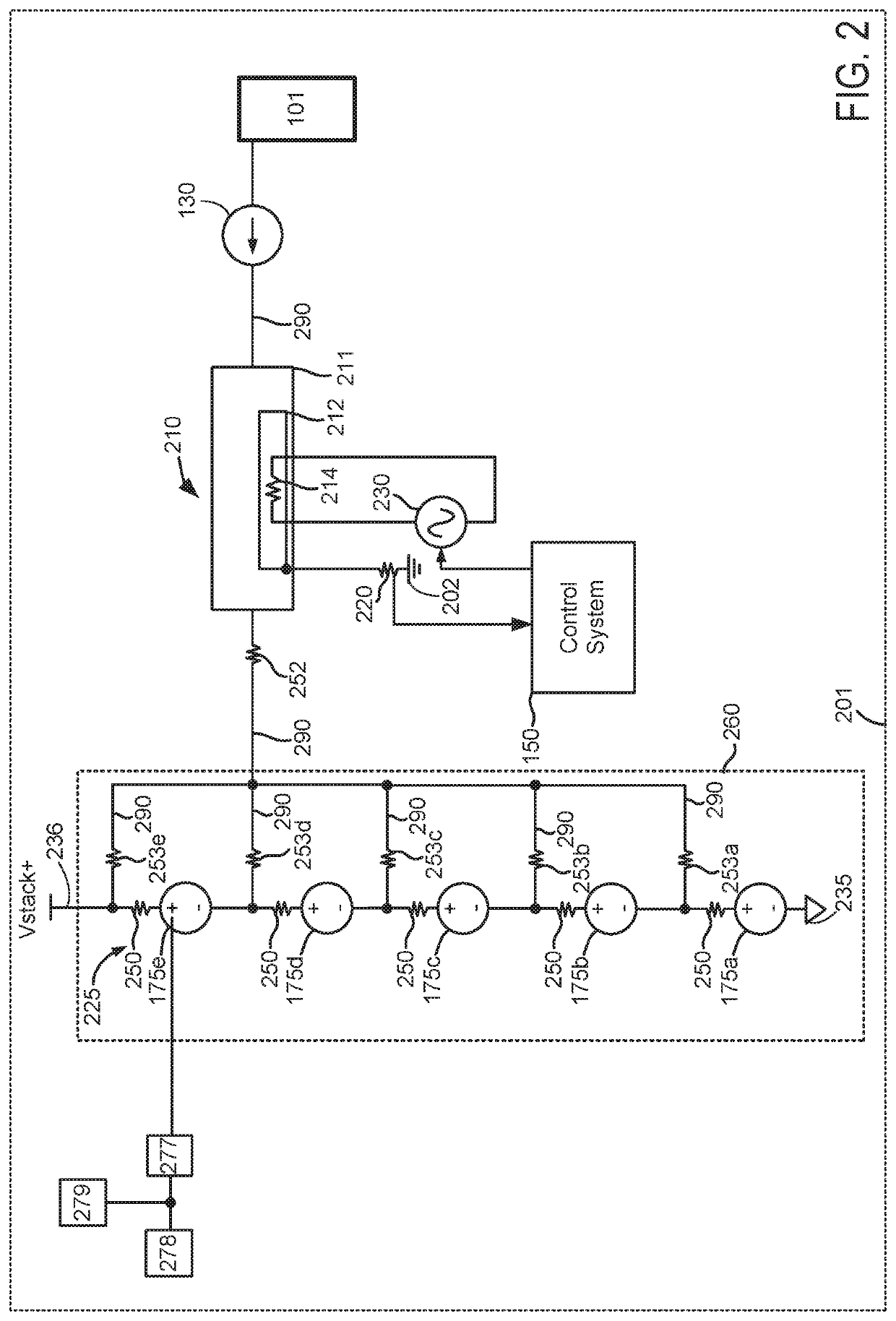
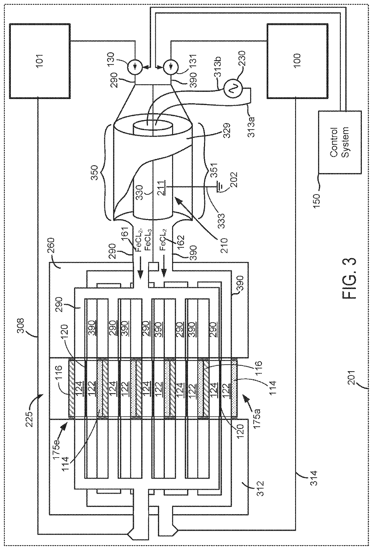
[0016]The present description is related to storing and delivering power via an electric energy storage device (e.g., a direct current (DC) power source) as shown in FIG. 1. The electric energy storage device may store electrical energy that is generated via photovoltaic cells, hydroelectric power, wind power, or via chemical energy. The electric energy storage device may output DC power that may be distributed as alternating current AC after a conversion process. The electric energy storage device may be an iron flow device as shown in FIGS. 1-6. The electric energy storage device may include a heater that is referenced to ground as shown in FIGS. 2 and 3. Alternatively, an electrolyte distribution manifold may be referenced to earth ground as shown in FIG. 4 to reduce an electrical potential between the electric energy storage device and a reference electrical potential (e.g., earth ground). In still other examples, a pump housing or impeller may be electrically coupled to a refer...


PUM

PropertyMeasurementUnit
electrical potentialaaaaaaaaaa
metallicaaaaaaaaaa
electrical currentaaaaaaaaaa

Abstract

Systems and methods for operating an electric energy storage device are described. The systems and methods may reduce a voltage potential between a ground reference and terminals of an electric energy storage device. By lowering the voltage potential, a possibility of unintentionally discharging the electrical energy storage device to ground may be reduced.

Description

FIELD[0001]The present description relates to a system and method for sinking or sourcing electric power to or from an electric energy storage device. The methods and systems may be particularly useful for electrical power systems that include two electrolytes that are not in fluidic communication.BACKGROUND AND SUMMARY[0002]An electrical energy storage device may store electrical power that has been generated via an array of photovoltaic cells, wind turbines, hydroelectric generators, or other sources so that the electrical power may be delivered to electrical loads at a later time when output of the electrical power source may be low or when electrical loads are high. The electrical energy storage device may be comprised of a plurality of cells that may be coupled in series to increase the electrical potential of the electrical energy storage device. The electrical energy storage device may also include cells that are electrical coupled in parallel to increase the output capacity ...

Claims


Application Information

Patent Timeline
Patent Type & Authority Patents(United States)
IPC IPC(8): H01M8/04186H01M8/18H01M8/04276H01M8/04955H01M8/04537
CPCH01M8/04186H01M8/04276H01M8/04574H01M8/04955H01M8/188H01M8/04037H01M8/04201Y02E60/50
Inventor WALKER-STERN, ISAACVANDERZANDEN, AARON
Owner ESS TECHNOLOGY
Why Eureka
Try Eureka