Tubular volatizing device

a volatizing device and tube technology, applied in the direction of gaseous substances, inhalators, other medical devices, etc., can solve the problems of uncontrolled release of vapor, length of time, size, mass and cost of devices with any type of control, and achieve the effect of reducing the amount of material needed and reducing the preparation and warm up tim

Pending Publication Date: 2021-01-14
DYNAVAP LLC
View PDF4 Cites 1 Cited by
  • Summary
  • Abstract
  • Description
  • Claims
  • Application Information

AI Technical Summary

Benefits of technology

[0006]To that end, according to one aspect of the present disclosure a volatizing device is provided in which the device decreases the preparation and warm up time necessary to volatize the desired compounds from the material and additionally decreases the amount of material necessary to obtain the desired quantity of extract from the device because the cap keeps the vapor contained there is only a minute amount of vapor released unless suction is applied. In addition, the device provides a means for an accurate indication when the heat applied to the device reaches the proper level for the volatization of the desired compounds from material held within the device. The device of the present disclosure employs a heat source controlled by the user and an indicating mechanism with one or more of the following functions conveying tactile and audible thermo indications by utilizing a snap disk or other thermal indicator. The thermo-indicator is constructed of a material or in a manner enabling the indicator to provide an indication to the user of the volatizing device that the temperature within the device has reached a level sufficient to volatize the selected compound from the material contained within the device. Preferably, but not in every event or usage of the device or components thereof, the desired compound is volatized from the material without combusting the material to avoid the extraction of undesired compounds from the material, such as by limiting the temperature to that at which the desired compounds are volatized and extracted, but below the temperature at which the material undergoes combustion.
[0007]The tactile nature of the indicator in the device of the present disclosure allows for the conveyance of activation temperature in environments where audible and or visual only indicators would be less effective or desirable. A slightly more complex design of the new device could incorporate a thermistor, or other solid state or mechanical indicator such as a magnet assembly, thermocouple, or thermal pile which will create a visual, audible, vibrational, mechanical, electrical, tactile or other signal to indicate proper temperature. The tactile, vibrational or kinesthetic nature of the described indicator allows for accurate use in loud, dark, bright or other environments where devices with visual or audible only indicators would be undesirable or difficult to be conveyed by the device or detected by the user. In other embodiments, the cap can function independent of the body as well as functioning without the thermal indicator and or other heat transference related components, but to a lesser degree of accuracy and higher propensity of over and or under extraction including a more likely initiation of combustion.

Problems solved by technology

Some of the drawbacks of these prior art devices include: (1) the challenge to determine when the sample material contained within the chamber has achieved volatilizing temperature; (2) whether heat is over applied to the chamber and the material, resulting in the creation or release of undesired compounds or potentially burning the sample material creating combustion byproducts in addition to the release of these undesired compounds, along with; (3) the length of time it takes to heat the device and or material to reach volatizing temperature; and (4) there commonly is an uncontrolled release of vapor, potentially containing target compounds prior to extraction of target compounds; (5) the size, mass and cost of devices with any type of control.
In addition, prior art vaporization devices do not have multifunction caps.
Prior art devices that do not contain their own heat source have no means of regulating temperature.
As a result, these prior art devices are more complex, with significant additional cost and manufacturing complexity as well as increased size and weight added to the device, therefore making the prior art devices more expensive to produce and more prone to failure.
The tactile, vibrational or kinesthetic nature of the described indicator allows for accurate use in loud, dark, bright or other environments where devices with visual or audible only indicators would be undesirable or difficult to be conveyed by the device or detected by the user.

Method used


Image

  • Tubular volatizing device
  • Tubular volatizing device
  • Tubular volatizing device

Examples


Embodiment Construction

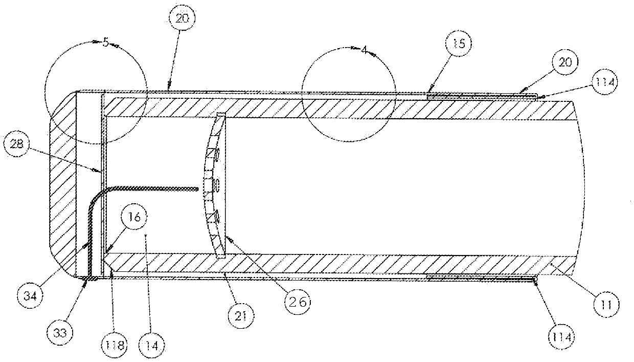
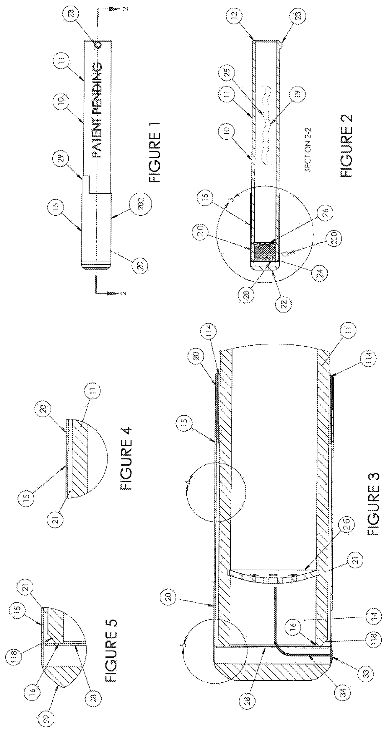
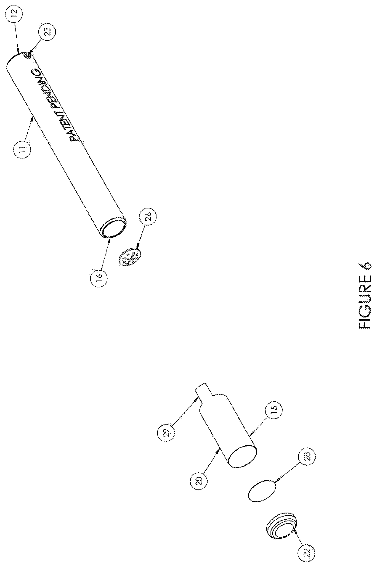
[0039]Referring now in detail to the drawing figures, wherein like reference numerals represent like parts throughout the several views, one embodiment of a volatizer constructed according to the present disclosure is illustrated generally at 10 in FIG. 1. The volatizer 10 includes a body or tube 11 that is formed of any suitable material, such as glass, ceramic, metal or composite, inorganic composite, among others, and is generally tubular but not necessarily round in shape. Shapes may be but are not limited to triangular, square or rectangular. In one embodiment, the body 11 is formed of glass in order to enable the body 11 to retain and diffuse heat from the heat source 200, such as a lighter or flame, applied to the body 11 and the cap 15 at the heat ring(s) 32 or hot spot(s) 33. The heat ring(s) 32 or hot spot(s) 33, is a marking, and or location identified as the best area to apply heat to facilitate the best transfer of heat form the heat source 200 to the chamber 14 and the...


PUM

PropertyMeasurementUnit
temperatureaaaaaaaaaa
inner diameteraaaaaaaaaa
outer diameteraaaaaaaaaa

Abstract

A volatizer is provided including a multifunction cap secured over the open end of a body or other device, the chamber or other part of the device holding an amount of material to be extracted by selective volatization therein and including a thermo-indicator thereon or therein capable of deforming, actuating or otherwise indicating upon heating to a preselected temperature to provide an indication of the proper temperature for volatilization and extraction of the selected and or target compound from the material within the device. Also provided is a method of volatizing a substance.

Description

RELATED APPLICATIONS[0001]This application is a division application of U.S. patent application Ser. No. 14 / 142,351 filed on Dec. 27, 2013, entitled “Tubular Volatizing Device,” the content of which is incorporated herein by reference.FIELD OF THE INVENTION[0002]The present invention relates generally to a volatizing extraction device, and more specifically to a volatizing device with an activation indicator(s).BACKGROUND OF THE INVENTION[0003]There are many devices designed to selectively vaporize or volatilize selected compounds from material placed within the device. In these previous devices, the vaporization chamber in which the material to be vaporized is connected, positioned and or secured to a tube to facilitate the evacuation of the volatilized compounds from the sample. The chamber is heated by applying heat from a flame or an electric element directly to the chamber. When the desired temperature is reached the target compounds from the sample within the chamber are vapor...

Claims


Application Information

Patent Timeline
Patent Type & Authority Applications(United States)
IPC IPC(8): A61L9/03H05B1/02A61M15/06A24F40/20A24F40/60
CPCA61L9/03H05B1/0291A61M11/047A61M2205/583A61M15/06A61M11/042A61M11/048A24F40/60A24F40/20
Inventor BREIWA, III, GEORGE R.
Owner DYNAVAP LLC
Why Eureka
Try Eureka