Vapor-liquid contactor, cryogenic air separation unit and method of gas separation

a technology of vapor-liquid contactor and cryogenic air separation unit, which is applied in the direction of lighting and heating apparatus, heating types, and separation processes, etc., can solve the problems of low vapor-liquid contact efficiency, high cost of apparatus production and construction, and difficulty in allowing liquid to flow

Inactive Publication Date: 2003-05-13
NIPPON SANSO CORP
View PDF20 Cites 15 Cited by
  • Summary
  • Abstract
  • Description
  • Claims
  • Application Information

AI Technical Summary

Benefits of technology

The vapor-liquid contactor according to the present invention uses as a packing a non-promoting-fluid dispersion type structured packing wherein thin sheets or tubes are laminated or arranged along the perpendicular direction in which various types of shapes for determining a flow direction of said liquid and vapor streams are formed over the perpendicular direction of thin sheet or tube. The vapor-liquid contactor includes at least one liquid distributor consisting of a rough distribution part to distribute the liquid roughly, and a minute distribution part to distribute the liquid minutely and equally. Accordingly, in the liquid distributor, the descending liquid is uniformly distributed over the whole cross-section of the column. Thereafter, in the non-promoting-fluid-distribution type structured packing wherein thin sheets or tubes formed in the perpendicular direction of flow streams are laminated or arranged in the perpendicular direction, a sufficient ascending vapor stream channel is assured by carrying out a vapor-liquid contact, a descending liquid in the surface of the packing is smoothly flowed and an uniformity of thin sheet is retained over the whole sections. The whole surfaces of the packing is effectively used. For this reason, an increase in the pressure loss due to an increase in a flow resistance of the ascending vapor can be reduced, a occurring of flooding can be prevented, a sufficient vapor-liquid contact area can be assured and an efficient distillation can be carried out. Accordingly, the load of the liquid and vapor can be established highly.
Further, the height of the column can be set lower. The costs required for the preparation and construction of the apparatus can be reduced. In addition, the product output can increased and reduced largely.

Problems solved by technology

Further, it may promote a dispersion of the liquid by providing corrugations and / or unevennesses and / or holes on the surface of the metal sheet.
However, there are disadvantages in the above packed column type of vapor-liquid contactor in that a higher column should be provided and costs for the production and construction of an apparatus are high, when compared to the sieve tray column type of vapor-liquid contactor having the identical liquid and vapor loads.
Also, when a vapor-liquid contactor having a self-promoting-fluid-dispersion type structured packing is used, it is difficult to allow the liquid to flow in the downward surface (reverse surface) of the inclined part of the packing whereby a vapor-liquid contact efficiency becomes low.
In contrast, in the vapor-liquid contactor using only a self-promoting-fluid dispersion type structured packing, at least a part of the thin sheet is inclined relative to the main flow direction (perpendicular direction); therefore, it is easy to occur a flooding under a high load, the descending liquid is difficult to flow in the backside (reverse side) of the inclined part, vapor-liquid contact area is not sufficient, and the distillation efficiency is lowered.
However, in the packing column, the inner pressure of the column generally tends to easily occur a flooding as the inner pressure of the column is increased.
It is difficult to apply the packing column to a high pressure column of the cryogenic air separation unit having a multiple distillation column.

Method used


Image

  • Vapor-liquid contactor, cryogenic air separation unit and method of gas separation
  • Vapor-liquid contactor, cryogenic air separation unit and method of gas separation
  • Vapor-liquid contactor, cryogenic air separation unit and method of gas separation

Examples


example 2

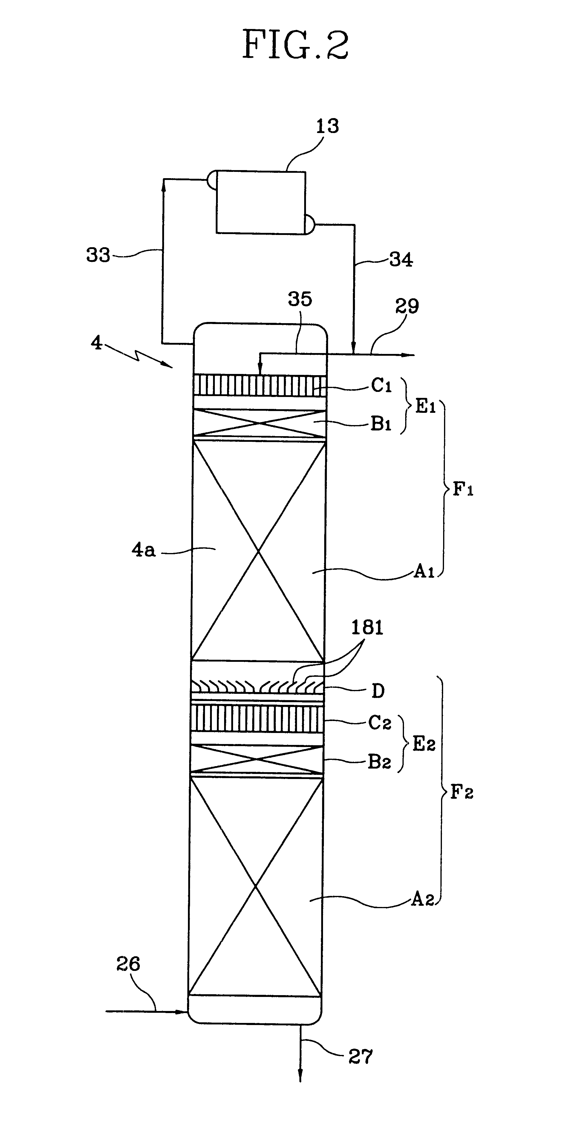
The following experiments were carried out by using a distillation column which is a vapor-liquid contactor shown in FIG. 28. This distillation column (inner diameter 208 mm, prepared from transparent vinyl chloride) includes a rough dispersion part C.sub.3, a minute distribution part B.sub.3, and a non-promoting-fluid-distribution type structured packing A.sub.3 over the bottom portion from the top portion of the column.

As the rough distribution part C.sub.3, the same part as shown in FIG. 4 was used. As the minute distribution part B.sub.3, the self-promoting-fluid dispersion type structured packing 2 elements denoted by the reference number 87 having a specific surface area of 500 m.sup.2 / m.sup.3 and a height of 100 mm, the parallel plane plate group 85 (height 50 men) as shown in FIG. 26, and a parallel plane sheet group 86 (height 50 mm) as shown in FIG. 27 were used in the order from the top portion.

In this case, two parallel plane sheet groups 85a, 86a of two parallel plane ...

example 3

As an example that a minute distribution part is mounted in the distillation column, the degree of dispersion of liquid under each condition was observed by using a distillation column of Example 2 shown in FIG. 28 and using as a fluid a freon having the same viscosity as air. Further, a liquid flow in the column and a pattern in liquid distribution was taken by a video.


PUM

PropertyMeasurementUnit
pressureaaaaaaaaaa
pressureaaaaaaaaaa
thicknessaaaaaaaaaa

Abstract

In an vapor-liquid contactor 4a for flowing down a liquid along the surface of a packing and contacting said liquid with the vapor while ascending the vapor, the improvement being characterized in that said packing is a non-promoting-fluid-dispersion type structured packing A1, A2 in which various types of thin sheets or tubes for determining the flow direction of the above liquid or vapor is laminated and arranged in the perpendicular direction, and said contactor includes at least one fluid distribution unit E1, E2 formed of a rough distribution part C1, C2 to distribute the liquid roughly and a minute distribution part B1, B2 to distribute the liquid minutely and equally.

Description

The present invention relates to a vapor-liquid contactor adapted to perform a vapor-liquid contact to thereafter separate gas mixture under a cryogenic distillation, and more particularly to a vapor-liquid contactor for use in the cryogenic air separation unit for carrying out a cryogenic separation of nitrogen, oxygen, argon from air, to a cryogenic air separation unit using the vapor-liquid contactor, and to a method of gas separation using the vapor-liquid contactor.TECHNICAL BACKGROUNDA distillation column used in a cryogenic air separation unit, etc. includes a packed column, a sieve tray column and the like. Among them, a packed column has an advantage of a low pressure loss (pressure drop) and a low operation cost with comparison to a sieve tray column. Further, the packed column has several advantages in that it can increase a relative volatility between each components of air by setting a low operation pressure according to its low pressure loss; the length of the column c...

Claims


Application Information

Patent Timeline
Patent Type & Authority Patents(United States)
IPC IPC(8): B01J19/32B01D3/14B01D3/20F25J3/04
CPCB01D3/20F25J3/04678F25J3/04909F25J3/04927F25J3/04412B01J19/32B01J2219/3221B01J2219/32213B01J2219/3222B01J2219/32227B01J2219/32244B01J2219/32248B01J2219/32258B01J2219/32262B01J2219/32272B01J2219/32279B01J2219/32286B01J2219/32296B01J2219/32408B01J2219/32483F25J2200/04F25J2200/90F25J2215/58F25J2290/10Y10S261/72F25J2250/02
Inventor HAYASHIDA, SHIGERUKIHARA, HITOSHIKAWAKAMI, HIROSHI
Owner NIPPON SANSO CORP
Why Eureka
Try Eureka