Silencer for refrigeration cycle system

a cycle system and silencer technology, applied in the direction of machines/engines, liquid fuel engines, light and heating apparatus, etc., can solve the problems of increasing the pressure loss of the silencer refrigerant, and achieve the effect of easy assembly, easy formation and simplified construction

Inactive Publication Date: 2009-04-09
DENSO CORP
View PDF19 Cites 30 Cited by
  • Summary
  • Abstract
  • Description
  • Claims
  • Application Information

AI Technical Summary

Benefits of technology

[0039]With this configuration, the inlet pipe (20) can be positioned with respect to the housing (16) by the protrusion (20a), and therefore can be easily assembled on the housing (16).
[0040]In this invention, the openings (21d, 20d) may be formed by cutting

Problems solved by technology

Therefore, in the latter conventional technique, the phenomenon describ

Method used


Image

  • Silencer for refrigeration cycle system
  • Silencer for refrigeration cycle system
  • Silencer for refrigeration cycle system

Examples


first embodiment

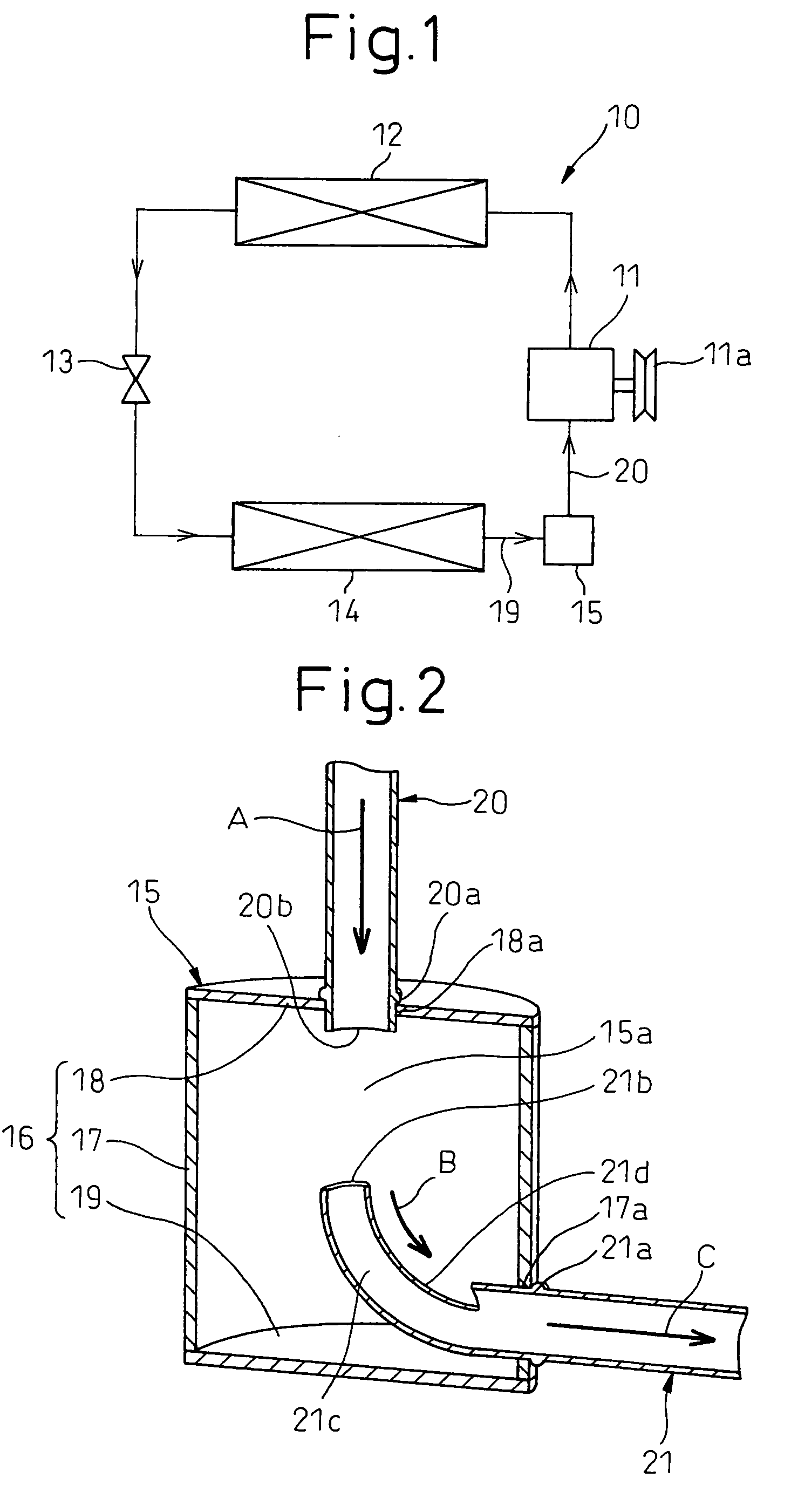
[0049]The first embodiment of the invention will be explained below with reference to FIGS. 1 and 2. FIG. 1 is a diagram showing the refrigerant circuit of the refrigeration cycle system 10 according to this embodiment. The refrigeration cycle system 10 according to this embodiment is applicable to an automotive air conditioning system.

[0050]In the refrigeration cycle system 10 according to this embodiment, a compressor 11 for sucking in and compressing the refrigerant is rotationally driven by the vehicle engine (not shown) through an electromagnetic clutch 11a and a belt.

[0051]The compressor 11 employed in this embodiment may be either a variable displacement refrigerant compressor capable of adjusting the refrigerant discharge capability with the change in the discharge capacity or a fixed displacement refrigerant compressor adapted to adjust the refrigerant discharge capability by switching on / off the electromagnetic clutch 11 and thus changing the operating efficiency of the co...

second embodiment

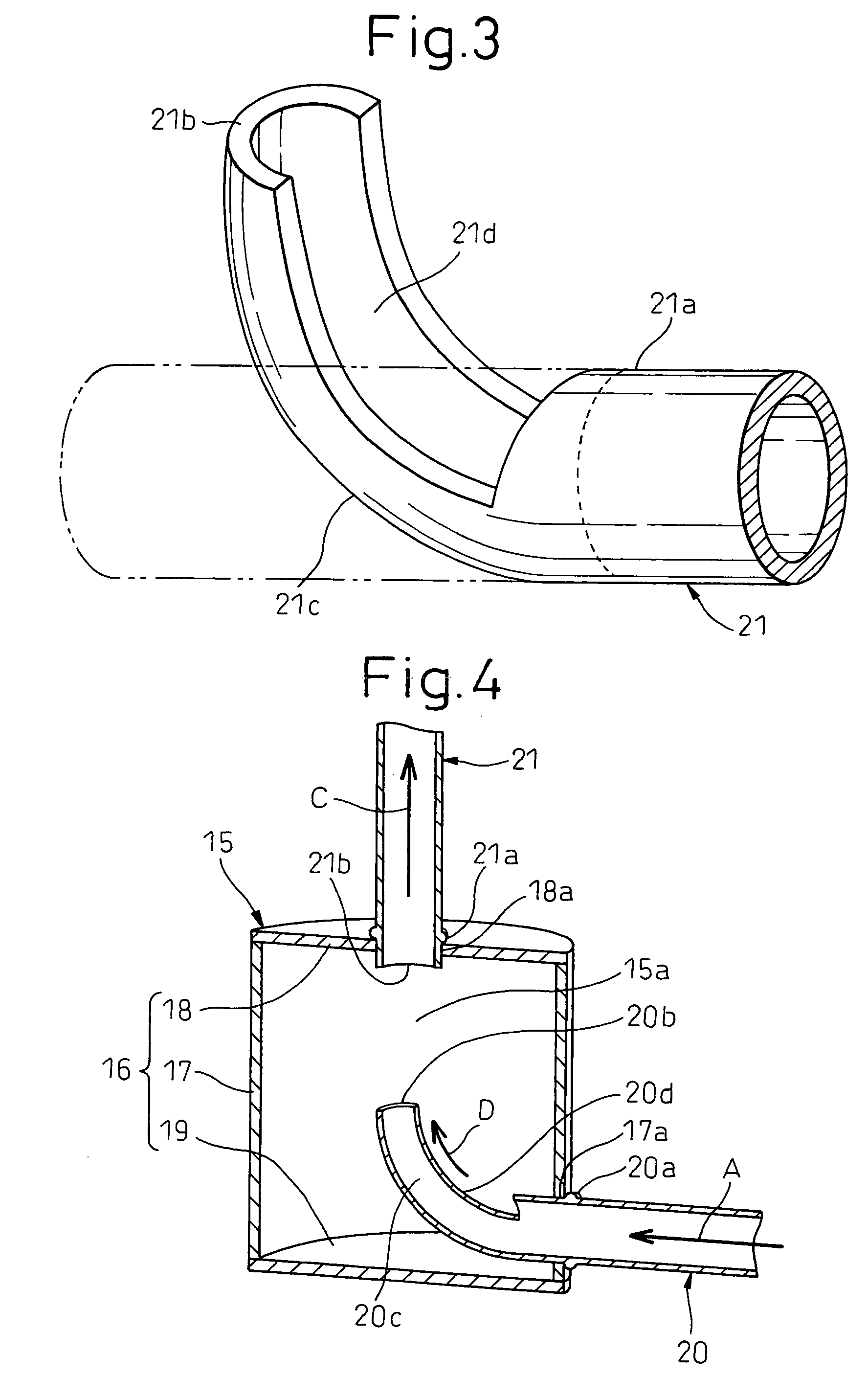
[0093]According to the second embodiment, as shown in FIG. 4, the relative positions of the inlet pipe 20 and the outlet pipe 21 are reversed from those of the first embodiment.

[0094]Specifically, the inlet pipe 20 is inserted into the opening 17a of the cylindrical portion 17 of the housing 16, while the outlet pipe 21 is inserted into the opening 18a of the lid 18 of the housing 16.

[0095]The bend 21c of the outlet pipe 21 is omitted, and a bend 20c projected into the silencing chamber 15a and curved about 90 degrees toward the upstream end 21b of the outlet pipe 21 is at the downstream end 20b portion of the inlet pipe 20.

[0096]This bend 20c is formed with an opening 20d for exposing the inner side portion of the bend 20c. The opening 20d is formed by cutting the inner pipe wall of the bend 20c.

[0097]According to this embodiment, the opening 20d is formed to extend from the downstream end 20b beyond the central portion of the bend 20c in the direction of refrigerant flow.

[0098]Th...

third embodiment

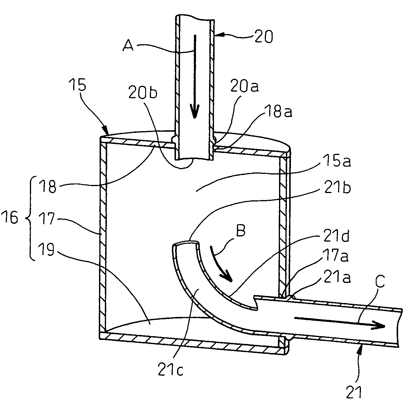
[0104]According to the first embodiment, the opening 21d is formed as a notch by cutting the upstream end 21b portion of the outlet pipe 21. On the other hand, according to the third embodiment, as shown in FIG. 5, the opening 21d is formed as a hole in the intermediate portion of the bend 21c in the direction of refrigerant flow.

[0105]This embodiment can also exhibit substantially the same operational effect as the first embodiment.

Other Embodiments

[0106]According to each embodiment described above, the direction in which the inlet pipe 20 is connected to the housing 16 is substantially orthogonal to the direction in which the outlet pipe 21 is connected to the housing 16. Nevertheless, the invention is not limited to this configuration. Instead, the direction in which the inlet pipe 20 is connected to the housing 16 and the direction in which the outlet pipe 21 is connected to the housing 16 may cross each other.

[0107]According to each embodiment described above, the silencing ch...


PUM


Abstract

A silencer for a refrigeration cycle system is disclosed. The silencer includes a silencing chamber 15a formed in a housing 16, an inlet pipe 20 connected to the housing 16 to allow the refrigerant to flow into the silencing chamber 15a, and an outlet pipe 21 connected to the housing 16 to allow the refrigerant to flow out of the silencing chamber 15a. The direction in which the inlet pipe 20 is connected to the housing 16 and the direction in which the outlet pipe 21 is connected to the housing 16 cross each other. A bend 21c projected into the silencing chamber 15a and curved toward the upstream end 20b of the inlet pipe 20 is formed at the upstream end 21b portion of the outlet pipe 21. The bend 21c is formed with an opening 21d to open the inside part thereof. As a result, the refrigerant that has flowed into the silencing chamber 15a can be guided smoothly to the outlet pipe 21 while at the same time avoiding a case in which the bend 21c suppresses the interference of the pressure wave.

Description

BACKGROUND OF THE INVENTION[0001]1. Field of the Invention[0002]This invention relates to a silencer for a refrigeration cycle system for reducing the pressure pulsation of a refrigerant discharged from a compressor.[0003]2. Description of the Related Art[0004]In the prior art, the silencer for this type of refrigeration cycle system is designed to reduce the pressure pulsation of a refrigerant by interference of the pressure wave in the silencing chamber (see, for example, Japanese Unexamined Patent Publications Nos. 2002-61508 and 11-62827).[0005]The conventional technique described in Japanese Unexamined Patent Publication No. 2002-61508 concerns a silencer which is known as a straight type for the refrigeration cycle system, in which the inlet pipe through which the refrigerant flows into the silencing chamber is aligned with the outlet pipe through which the refrigerant flows out of the silencing chamber. As a result, the refrigerant flows linearly in the silencing chamber.[000...

Claims


Application Information

Patent Timeline
IPC IPC(8): F01N1/00
CPCF04B53/001F25B2500/12F04C2240/806F04C29/065B60H1/00571B60H2001/006
Inventor NISHIDA, SHINKAWAKUBO, MASAAKIYAMANAKA, TAKASHI
Owner DENSO CORP
Why Eureka
Try Eureka