
Method for Manufacturing Plugged Honeycomb Structure

a technology of honeycomb and manufacturing method, which is applied in the direction of manufacturing tools, ceramicware, separation processes, etc., can solve the problems of reducing the strength difficult to uniformly fill the slurry into the cell, and different sizes of the plugged portion, so as to improve the trapping efficiency of particulate matter and reduce pressure loss

Inactive Publication Date: 2008-06-05
NGK INSULATORS LTD
View PDF9 Cites 30 Cited by
  • Summary
  • Abstract
  • Description
  • Claims
  • Application Information

AI Technical Summary

Benefits of technology

[0006]The longer the plugged portions in the cell passage (fluid passage) direction (i.e., depth of the plugged portions) are, the more the surface area of the partition walls where exhaust gas is filtrated reduces, and the more a pressure loss of the filter increases. Therefore, it is preferable to make the plugged portions as shallow as possible from the viewpoint of inhibiting the pressure loss from increasing. On the other hand, the shallower the plugged portions are, the more the strength of the plugged portions reduces, which sometimes causes damages due to thermal or mechanical stress, exfoliation of a plugged portion from a passage, or damages of plugged portions exposed on the front end face of the filter due to erosion by an exhaust gas flow. Therefore, in the case that each of a large number of plugged portions present in one filter is made shallow, it is required to uniformly fill the slurry into the cells to be plugged in a method for forming plugged portions because, when one of the plugged portions is excessively shallow, the above problem is caused in the plugged portion. This requires uniformity which is stricter when the plugged portions are shallower.
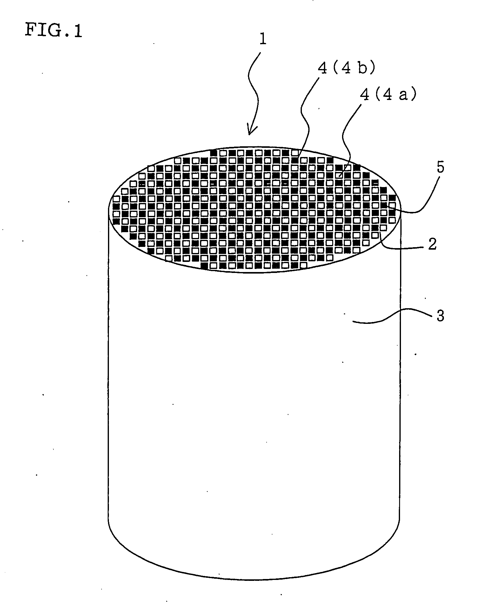
[0029]According to a method for manufacturing a plugged honeycomb structure of the present invention, there can easily be obtained a plugged honeycomb structure provided with a honeycomb structure which is suitably used as a filter for trapping and purifying particulate matter contained in exhaust gas exhausted from internal combustion engines such as a diesel engine or various kinds of combustion apparatuses and which has a plurality of cells functioning as fluid passages separated and formed by partition walls and with plugged portions where open end portions on one side of predetermined cells among the cells of the honeycomb structure and open end portions on the other side of the other cells are alternately plugged. In particular, in a method for manufacturing a plugged honeycomb structure of the present invention, since plugged portions having uniform depth can be formed in an open end portion of each of the cells, enhancement of trapping efficiency of particulate matter and reduction in pressure loss can be realized.

Problems solved by technology

On the other hand, the shallower the plugged portions are, the more the strength of the plugged portions reduces, which sometimes causes damages due to thermal or mechanical stress, exfoliation of a plugged portion from a passage, or damages of plugged portions exposed on the front end face of the filter due to erosion by an exhaust gas flow.
Therefore, in the case that each of a large number of plugged portions present in one filter is made shallow, it is required to uniformly fill the slurry into the cells to be plugged in a method for forming plugged portions because, when one of the plugged portions is excessively shallow, the above problem is caused in the plugged portion.
However, it is difficult to uniformly fill the slurry into the cells to be plugged by such a conventionally method, and a problem of having the resultant plugged portions having different sizes is caused.
However, in the case of using such a method, it is difficult to uniformly fill the slurry into the cells to be plugged, and therefore, there is a problem of causing a defect in a plugged portion.

Method used


Image

  • Method for Manufacturing Plugged Honeycomb Structure
  • Method for Manufacturing Plugged Honeycomb Structure
  • Method for Manufacturing Plugged Honeycomb Structure

Examples


example 1

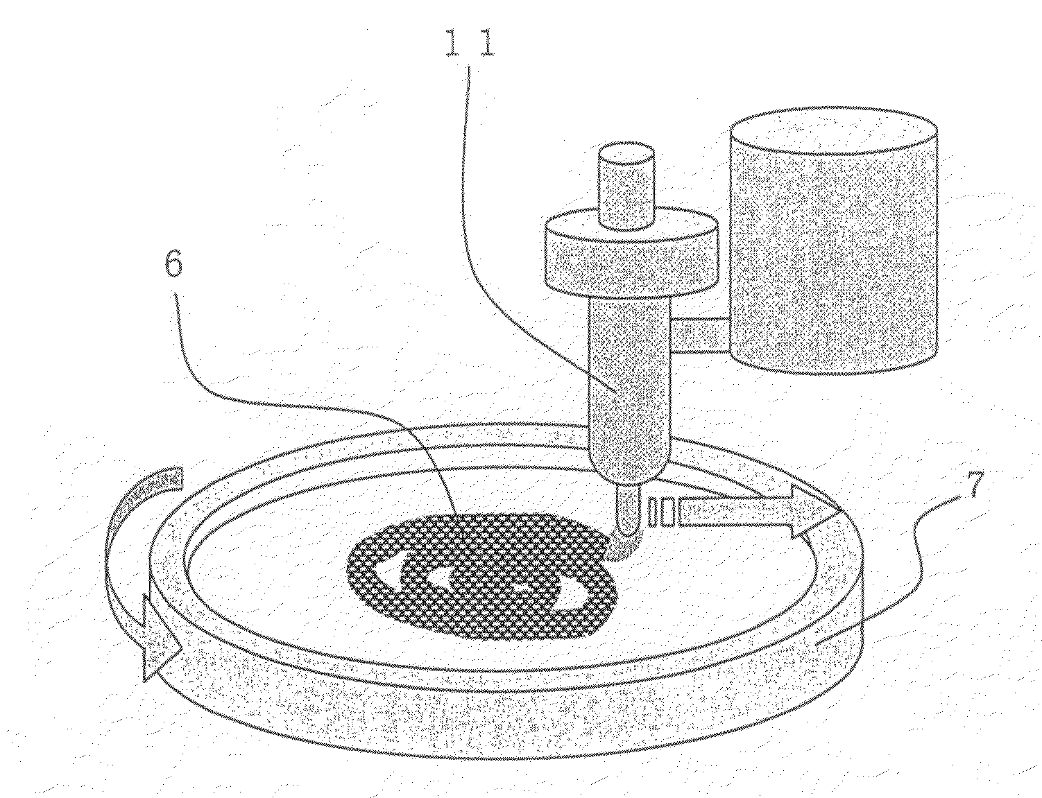
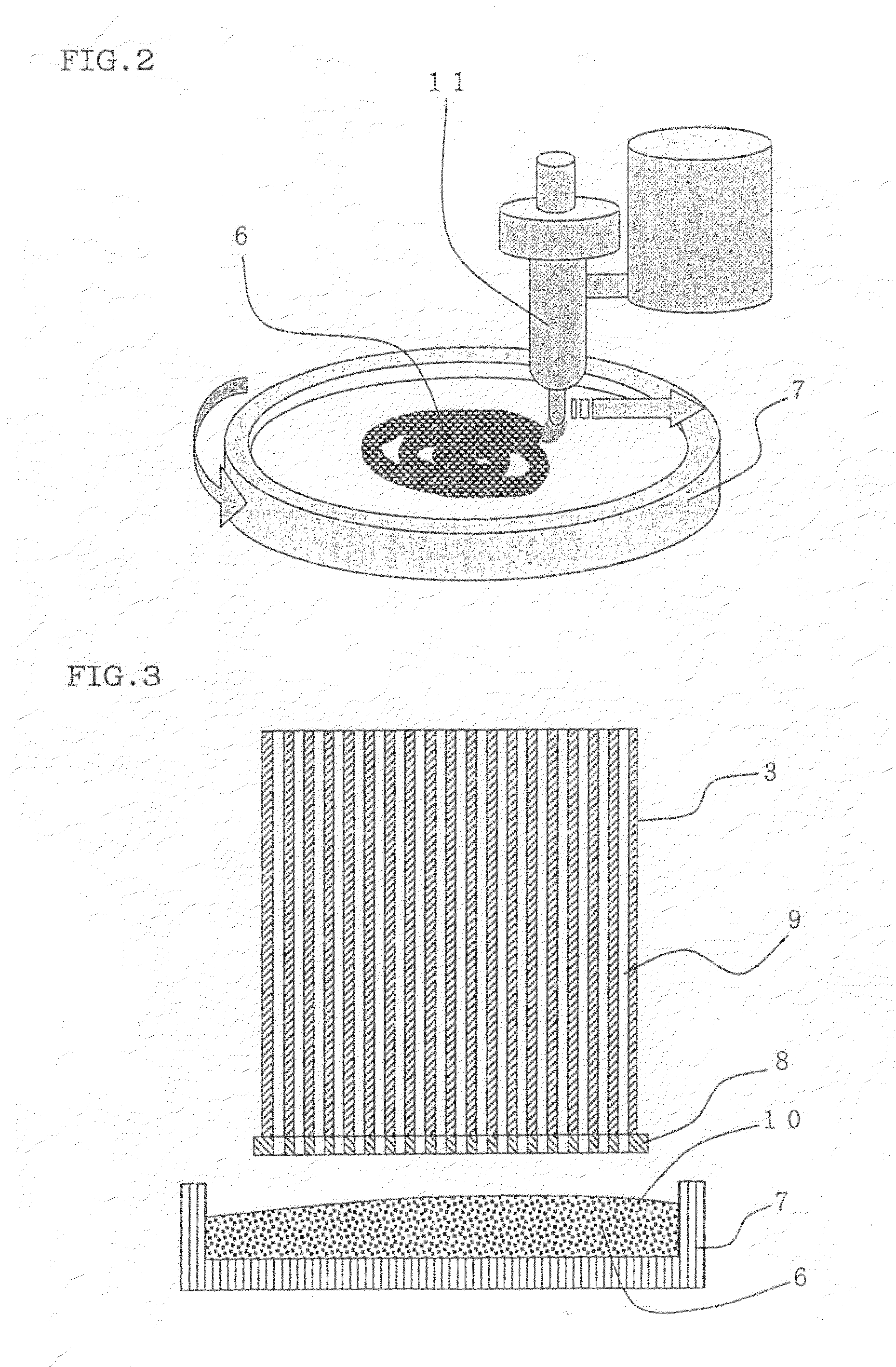
[0098]First, the aforementioned slurry was filled into a tank of a discharger, and slurry was discharged with moving the discharger with rotating a storage container for storing the slurry at a rotational frequency of 30 times per minute to store the slurry in the storage container in the form of swirl. Then, the storage container having the slurry therein was vibrated in a direction perpendicular to the bottom face. The interface of the slurry stored in a storage container had a flatness of 1.5 mm with respect to an end face of the honeycomb structure to be plugged.

[0099]Next, an end face on one side of a honeycomb structure having a mask for forming plugged portion disposed thereon was pressed against the slurry stored in the storage container to introduce the slurry in the cells to be plugged from holes in the mask for forming plugged portions. The same steps were taken with respect to the other end face. Then, the introduced slurry was dried and fired to manufacture a plugged ho...


PUM

PropertyMeasurementUnit
Viscosityaaaaaaaaaa
Lengthaaaaaaaaaa
Lengthaaaaaaaaaa

Abstract

There is provided a method for manufacturing a plugged honeycomb structure, where slurry 6 functioning as a raw material for the plugged portions is stored in a storage container 7 so that the slurry 6 may have a flat interface, and the plugged portions are formed by pressing an end face of the honeycomb structure 3 having a mask 8 for forming plugged portions disposed so as to cover open end portions of the cells other than the cells 9 to be plugged of the honeycomb structure 3 against the slurry 6 stored in the storage container 7 to introduce the slurry 6 into the inside of the cells 9 to be plugged.

Description

TECHNICAL FIELD[0001]The present invention relates to a method for manufacturing a plugged honeycomb structure. More particularly, the present invention relates to a method for manufacturing a plugged honeycomb structure provided with a honeycomb structure which is suitably used as a filter for trapping and purifying particulate matter contained in exhaust gas exhausted from internal combustion engines such as a diesel engine or various kinds of combustion apparatuses and which has a plurality of cells functioning as fluid passages separated and formed by partition walls and with plugged portions where open end portions on one side of predetermined cells among the cells of the honeycomb structure and open end portions on the other side of the other cells are alternately plugged.BACKGROUND ART[0002]Exhaust gas exhausted from internal combustion engines such as a diesel engine or various kinds of combustion apparatuses contains a large amount of particulate matter mainly composed of s...

Claims


Application Information

Patent Timeline
IPC IPC(8): B32B37/10
CPCB01D46/2418B01D46/2451B01D46/2466B01D2046/2496B01D2279/30B28B11/006B28B11/007C04B2111/00793C04B38/0012C04B35/195C04B38/0051B01D46/2498
Inventor MASUDA, MASAHIROICHIKAWA, YUKIHITO
Owner NGK INSULATORS LTD
Learn More