

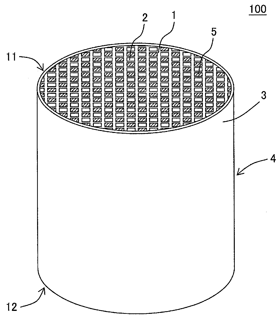
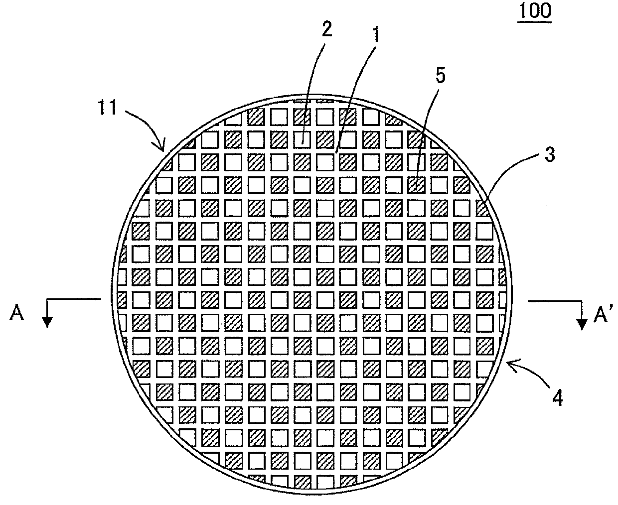
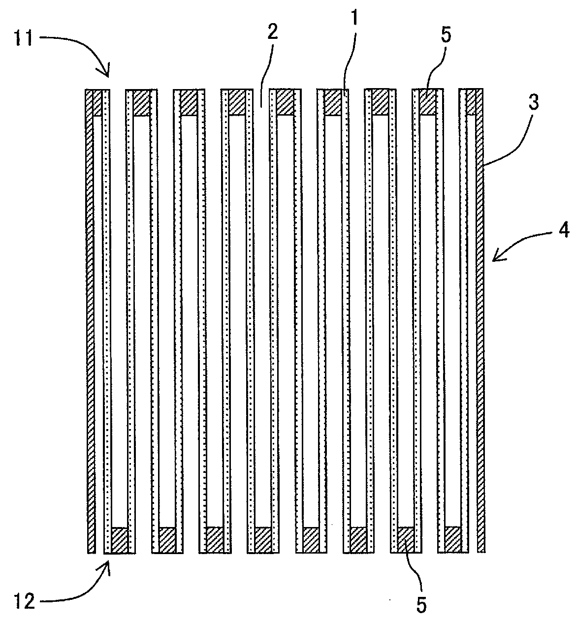
Plugged honeycomb structure
a honeycomb structure and plug-in technology, applied in the field can solve the problems of plurality of manufactured such plugged honeycomb structures, and low pressure loss of plugged honeycomb structures, and achieves small variation in pressure loss, suppresses pressure loss variations, and excellent trapping performance.
- Summary
- Abstract
- Description
- Claims
- Application Information
AI Technical Summary
Benefits of technology
Problems solved by technology
Method used
Image

Examples
example 1
[0071]As the raw material powder to prepare kneaded material, silicon carbide (SiC) powder and metal silicon (Si) powder were mixed at the mass ratio of 80:20 to prepare a mixed raw material.
[0072]7 parts by mass of binder, 25 parts by mass of pore former, and 42 parts by mass of water were added to 100 parts by mass of this mixed raw material to produce a forming raw material to prepare a kneaded material. Methylcellulose was used as the binder. For the pore former, pore former A having a particle diameter, which has the average pore diameter of 21 μm after firing, and pore former B having a particle diameter, which has the average pore diameter of 17 μm after firing, were blended at 1:1.
[0073]Next, the obtained forming raw material was kneaded by a kneader, thus preparing a kneaded material. Next, the obtained kneaded material was formed using an extruder to produce sixteen honeycomb formed bodies each having a quadrangular-prism shape. Next the obtained honeycomb formed bodies we...
examples 2 to 7
[0101]As shown in Table 1, plugged honeycomb structures were manufactured while changing their porosity and pore diameter obtained from the cumulative pore volume. The porosity and the pore diameter (i.e., the cumulative pore volume) were controlled by adjusting the particle diameter and the amount of the pore former added to the forming raw material.
[0102]In Example 2, for the pore former, pore former C having a particle diameter, which has the average pore diameter of 23 μm after firing, and pore former A having a particle diameter, which has the average pore diameter of 21 μm after firing, were blended at 1:1.
[0103]In Example 3, for the pore former, pore former D having a particle diameter, which has the average pore diameter of 27 μm after firing, and pore former E having a particle diameter, which has the average pore diameter of 16 μm after firing, were blended at 1:1.
[0104]In Example 4, for the pore former, pore former F having a particle diameter, which has the average pore ...
examples 8 to 13
[0108]As shown in Table 3, the plugged honeycomb structures of these Examples were manufactured similarly to Example 1 other than that the thickness of the partition walls was changed.
PUM
| Property | Measurement | Unit |
|---|---|---|
| pore diameter D10 | aaaaa | aaaaa |
| pore diameter D90 | aaaaa | aaaaa |
| pore diameter D10 | aaaaa | aaaaa |
Abstract
Description
Claims
Application Information