Electrical apparatus, cooling system therefor, and electric vehicle

a technology for electric vehicles and cooling systems, applied in electrical apparatus construction details, electrical propulsion mounting, transportation and packaging, etc., can solve the problems of increasing increasing the pressure, and increasing the loss, so as to increase the load on the pump and increase the pump size

Inactive Publication Date: 2006-08-15
HITACHI LTD
View PDF6 Cites 34 Cited by
  • Summary
  • Abstract
  • Description
  • Claims
  • Application Information

AI Technical Summary

Benefits of technology

[0005]However, according to the examination by the present inventors, of the structure disclosed in the JP-A 10-22428, it was found that this structure involves a problem of increasing the loss of pressure in the liquid path thereof. Specifically, the structure set forth in the JP-A 10-22428 is one in which the depth of liquid path in the fin rows is less than that in the cooling medium flow inlet. In addition, respective accumulating parts are provided between the inlet liquid path and the liquid path in the fin rows, and between the liquid path in the fin rows and the outlet liquid path. Therefore, in the respective accumulating parts, the liquid path depth steeply changes between the inlet liquid path and the liquid path in the fin rows, thereby causing a loss of pressure, and likewise, the liquid path depth steeply changes between the liquid path in the fin rows and the outlet liquid path, thereby incurring a pressure loss. These pressure losses increase the load on a pump for feeding the cooling medium into the liquid path. This raises a problem of increasing the size of the pump.
[0006]Accordingly, it is an object of the present invention to provide an inverter apparatus having a liquid path structure that allows uniform cooling without the need for accumulating parts to thereby improve the thermal characteristic, and that reduces the loss of pressure in the liquid path.
[0007]The present invention provides an electric apparatus having a flow structure for allowing uniform cooling to be achieved without the need for accumulating parts, thereby improving thermal characteristic, and also enables the pressure loss in the parts other than the cooling part to be reduced. Further, the present invention provides a cooling system and an electric vehicle for the electrical apparatus.
[0009]By virtue of these features, the present invention allows uniform cooling to be achieved without the need for accumulating parts, thereby improving thermal characteristic, and also enables the pressure loss in the parts other than the cooling part to be reduced.

Problems solved by technology

However, according to the examination by the present inventors, of the structure disclosed in the JP-A 10-22428, it was found that this structure involves a problem of increasing the loss of pressure in the liquid path thereof.
Therefore, in the respective accumulating parts, the liquid path depth steeply changes between the inlet liquid path and the liquid path in the fin rows, thereby causing a loss of pressure, and likewise, the liquid path depth steeply changes between the liquid path in the fin rows and the outlet liquid path, thereby incurring a pressure loss.
These pressure losses increase the load on a pump for feeding the cooling medium into the liquid path.
This raises a problem of increasing the size of the pump.

Method used


Image

  • Electrical apparatus, cooling system therefor, and electric vehicle
  • Electrical apparatus, cooling system therefor, and electric vehicle
  • Electrical apparatus, cooling system therefor, and electric vehicle

Examples


first embodiment

[0032]The construction of an inverter apparatus according to the present invention will be described below in connection with FIGS. 1 to 5.

[0033]First, references will be made to the overall construction of the inverter apparatus according to the first embodiment with reference to FIG. 1. The liquid-cooling inverter according to this embodiment is used as an on-board inverter for vehicles such as vehicles contributing environmental safeguard.

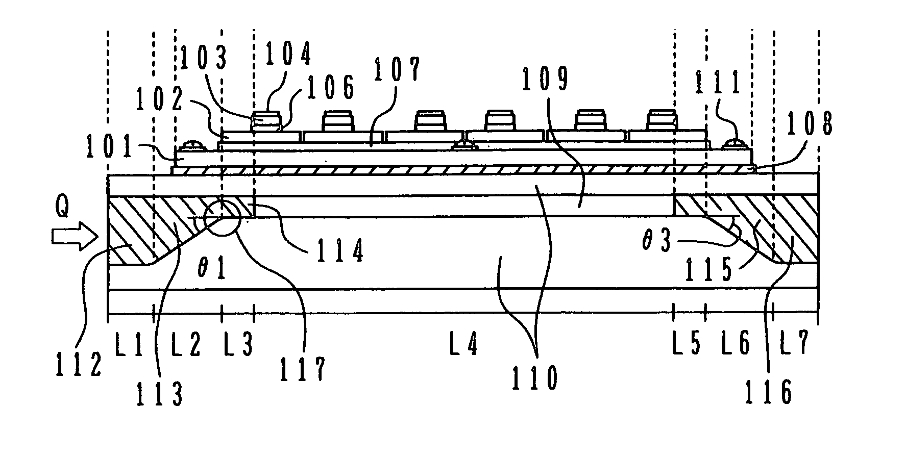
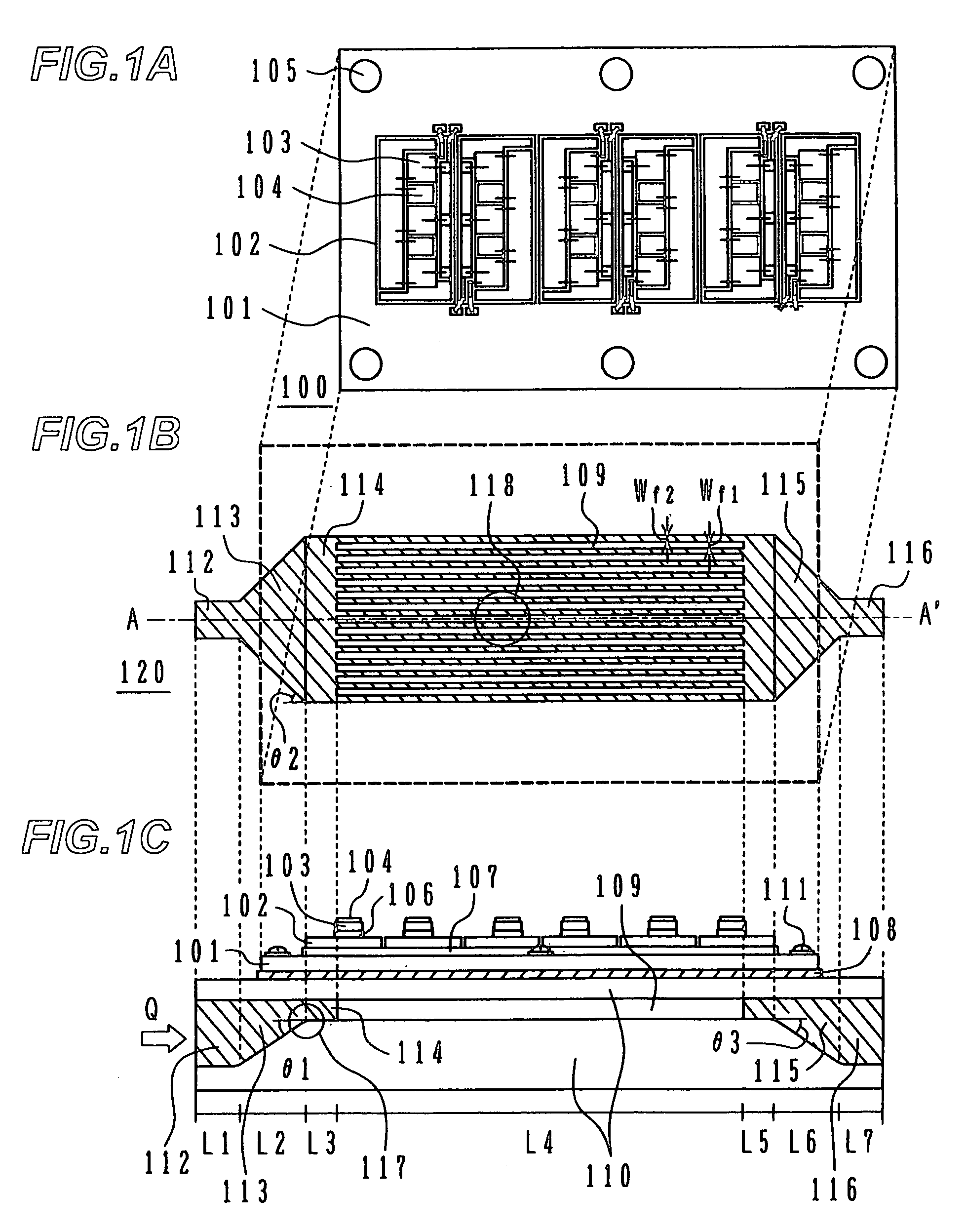
[0034]FIG. 1A is a plan view showing a module with six arms (upper and lower arms in each of the U, V, and W phases) of the inverter apparatus according to the first embodiment of the present invention, and FIG. 1B is a perspective plan view showing the liquid path part of this inverter apparatus. FIG. 1C is a sectional view showing the overall construction of the inverter apparatus, the sectional view being taken along the line A–A′ in FIG. 1B.

[0035]As shown in FIG. 1A, the module 100 includes semiconductor chips 103 and 104, substrates 102, an...

second embodiment

[0063]Next, the construction of an inverter apparatus according to the present invention will be described with reference to FIG. 6. The overall construction of the liquid-cooling inverter according to this embodiment is the same as that shown in FIG. 1.

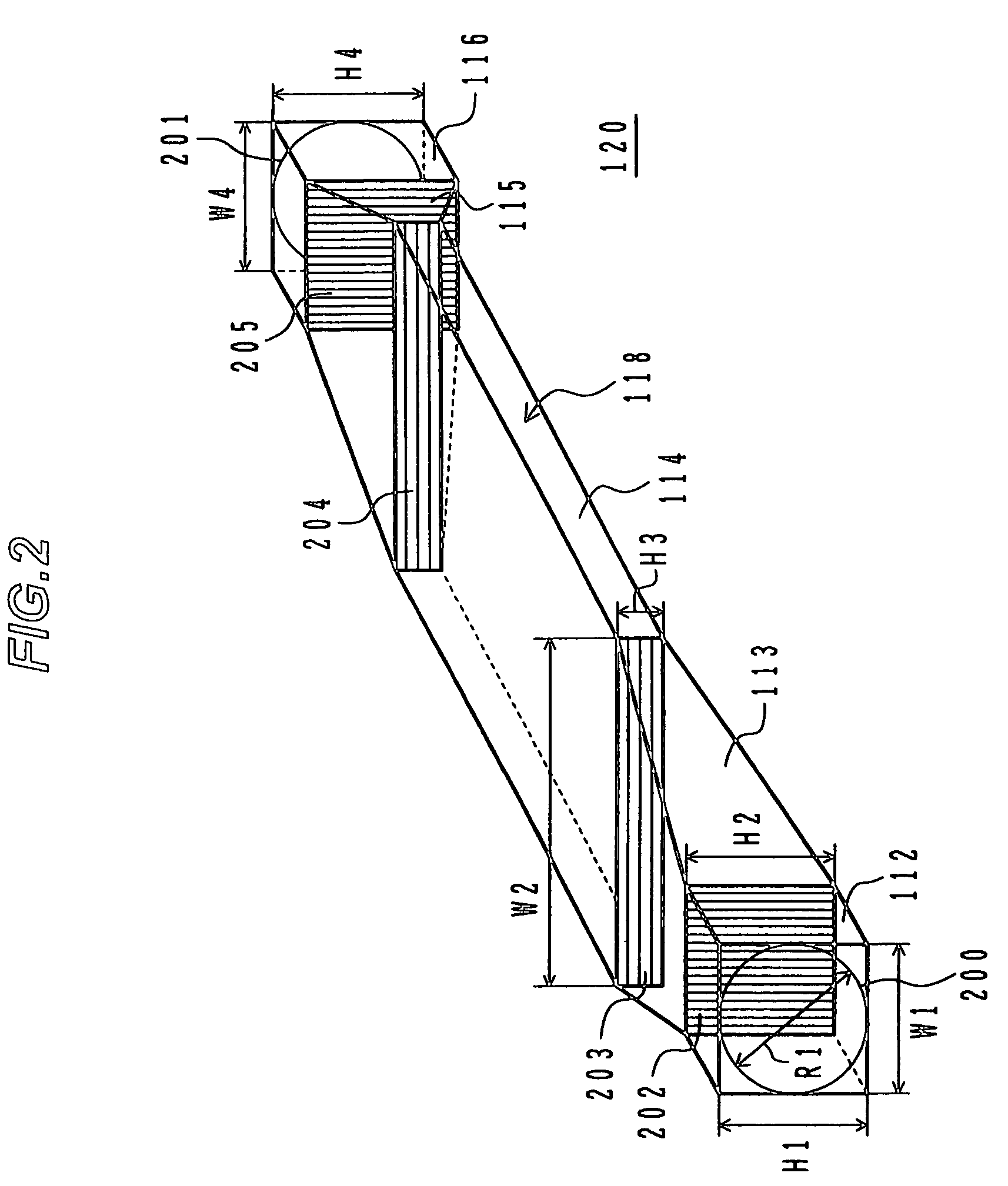
[0064]FIG. 6 is a perspective view showing the configuration of the liquid path in the inverter apparatus according to the second embodiment. In FIG. 6, the same reference numerals denote the same parts as those in FIG. 2.

[0065]A feed pipe 501 and drain pipe 504 constituting a liquid path 500, respectively, are cylinders having the same diameters as those of the feed pipe inlet 200 and the drain pipe outlet 201. A partial structure part 502 is configured to be gradually enlarged from a liquid path cross-section 505 up to a liquid path cross-section 506 in the liquid path width direction, and gradually reduced in the liquid path depth direction. On the other hand, a partial structure part 503 is configured to be gradually reduced from...

third embodiment

[0068]Next, the construction of the inverter apparatus according to the present invention will be described with reference to FIGS. 7A to 7C.

[0069]FIG. 7A is a plan view showing a module with six arms (upper and lower arms in each of the U, V, and W phases) of an inverter apparatus according to the third embodiment, and FIG. 7B is a perspective plan view showing the liquid path part of the inverter apparatus according to this embodiment. FIG. 7C is a sectional view showing the overall construction of the inverter apparatus according to this embodiment, the sectional view being taken along the line B–B′ in FIG. 7B. In FIG. 7A to 7C, the same reference numerals denote the same parts as those in FIG. 1.

[0070]The inverter apparatus according to this embodiment is used as a water-cooling inverter having the configuration of a base-direct-cooling module with fins. Specifically, fins 602.are integrally formed with a copper base 601. An opening part is formed at the center of the upper part...


PUM


Abstract

An inverter apparatus includes a liquid path in which cooling water flows, and in which the cooling water performs cooling at a cooling part located directly underneath the power circuit part of the inverter apparatus. The liquid path includes a first partial structure part formed between a feed pipe and the cooling part, and having a liquid path cross-sectional profile that is gradually reduced in the short-side direction of the cooling part and that is gradually enlarged in the long-side direction thereof; and a second partial structure part formed between the cooling part and a drain pipe, and having a liquid path cross-sectional profile that is gradually enlarged from the short-side of the cooling part and that is gradually reduced from the long-side thereof.

Description

BACKGROUND OF THE INVENTION[0001]1. Field of the Invention[0002]The present invention relates an electrical apparatus, a cooling system therefor, and electric vehicle inverter apparatus, and more particularly to an inverter apparatus characterized by the liquid path structure in the power circuit part in a liquid-cooling inverter.[0003]2. Description of the Related Art[0004]As an example of a conventional electric apparatus having a liquid path including a space for allowing a cooling medium for cooling a heating member to flow therein, for example, a conventional liquid-cooling inverter, an inverter as shown in FIG. 8 in JP-A 10-22428, is known in which a plurality of rows of fins is formed on the surface of a module's substrate adjacent to a cooling medium chamber, in which the fin rows are arranged with the direction from the inlet of the cooling medium flow toward the outlet thereof being the longitudinal direction, and in which the fins are formed as a contiguous sequence of fi...

Claims


Application Information

Patent Timeline
Patent Type & Authority Patents(United States)
IPC IPC(8): H05K7/20H01L23/473H02M7/00
CPCB60H1/00392B60H1/00428B60L15/007H01L23/473H02M7/003H05K7/20927B60L2240/525H01L2924/0002H01L2924/00Y02T10/64Y02T10/88
Inventor NAKAMURA, TAKAYOSHITAMBA, AKIHIROSAITO, RYUICHINISHIHARA, ATSUO
Owner HITACHI LTD
Why Eureka
Try Eureka