Garment badge holder

a badge and badge technology, applied in the field of badge holders, can solve the problems of pocket bulging out from the garment, premature failure of the pocket, and the cost of replacement or repair of the pocket may increas

Active Publication Date: 2019-12-31
PASSMAN ENTERPRISES
View PDF43 Cites 1 Cited by
  • Summary
  • Abstract
  • Description
  • Claims
  • Application Information

AI Technical Summary

Benefits of technology

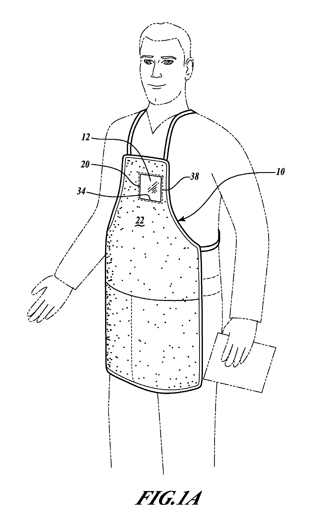
[0003]Typically, a badge holder is sewn, glued or clipped to an exterior of a garment. The badge holder can have a pocket that receives a card or a badge. The card or the badge can contain information that can, for example, identify an employee with a name and a company name. The pocket is disposed on and only accessible from an exterior of the garment. Motion of the wearer may cause a portion of the garment to gather or bunch, which may cause the pocket to bulge out from the garment. A bulging pocket that extends from the exterior of the garment may have a higher propensity to catch on or snag certain items that could tear or otherwise damage the pocket. Moreover, a pocket that extends from the exterior of the garment may encourage a user to store additional items in the pocket, such as a writing utensil, notepad, paperwork, or personal items, that may at least obscure the card or badge having their name and company name or lead to premature failure of the pocket. Replacement or repair of the pocket may become costly, especially when maintaining a large number of garments.
[0004]A successful solution to this problem is provided by commonly-owned U.S. Pat. No. 7,454,856 to Passman, issued on Nov. 25, 2008, which is hereby incorporated by reference. The '856 patent provides an interior-accessible pocket having advantageous construction. However, it has been found that several improvements can be made to provide enhanced performance, comfort, and ease of use.
[0030]Accordingly, in some embodiments, such as those illustrated in FIGS. 3C and 3E, badge 18 can be loaded into badge holder 12 via pocket opening 15 that is located along a top portion of badge holder 12. In this way, badge 18 can be slid into opening 15 and retained in position within pocket 14 at least by gravity and friction. Similarly, in some embodiments, as illustrated in FIG. 3F, badge 18 can be loaded into badge holder 12 via pocket opening 15 that is located along a side portion of badge holder 12 (e.g. left side or right side). In this way, badge 18 can be slid into opening 15 and retained in position within pocket 14 at least by gravity and friction. A side entry pocket 14 can be particularly useful in applications where the user will be bending over more frequently, which may cause the badge 18 to be improperly positioned within badge holder 12 in configurations permitting vertical movement thereby resulting in a badge that is not clearly visible from the exterior of the garment. However, in some embodiments, a top entry pocket 14 may be particularly convenient for insertion and access purposes. The benefits of each configuration may vary due to specific use and application.
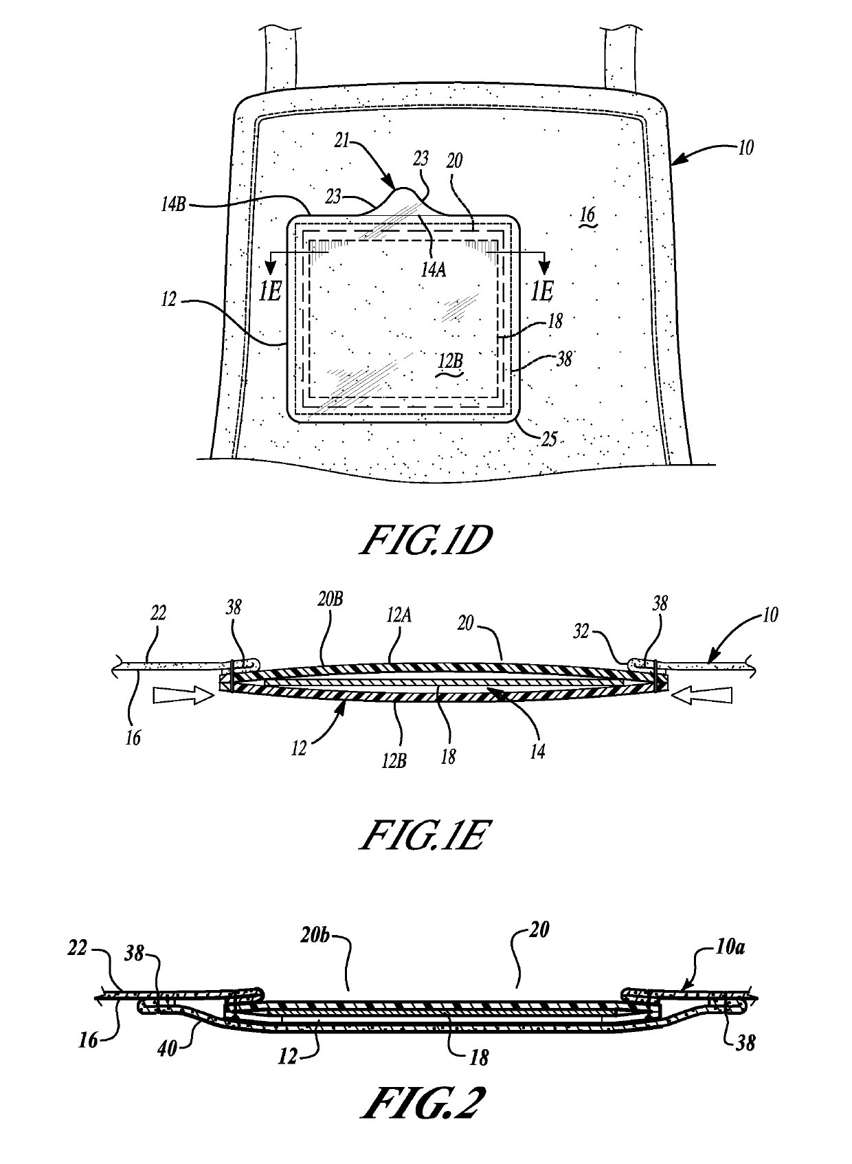
[0031]In some embodiments, interior panel 12B can comprise a tab feature 21 extending therefrom and continuous therewith to permit a user to conveniently grasp the tab feature 21 to reveal the opening of pocket 14 to aid in the insertion of badge 18. Tab feature 21 can be configured such that it extends beyond pocket edge 14A of exterior panel 12A and provides a gripping surface for users. Tab feature 21 can define any one of a number of designs to facilitate convenient grasping or gripping by the user. By way of non-limiting example, in some embodiments, tab feature 21 can define a centrally-disposed enlarged section have an arcuate transition 23 from pocket edge 14B of interior panel 12B. This embodiment provides a number of advantages, such as, but not limited to, removing any sharp corners that can lead to snags, minimizing the exposed edges to the user's clothing (e.g. only pocket edge 14B of interior panel 12B is exposed, as opposed to both pocket edges 14A and 14B of the previous embodiment), and eliminating the visual appearance of pocket edge 14B of interior panel 12B when viewed from the exterior of garment 10 (i.e. through the badge window).
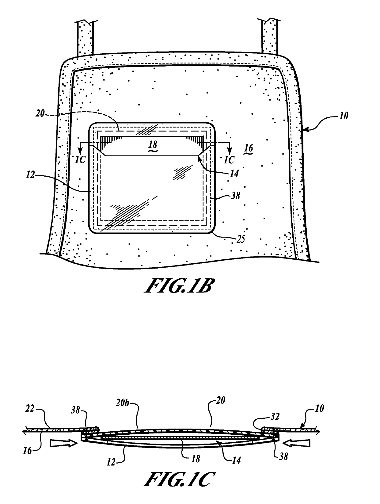
[0047]The badge holder 12 as affixed to the garment 10 in accordance with the present teachings can be shown to avoid the problem of having the pocket 14 tear away from a remaining portion of the badge holder 12. It can be shown that affixing the badge holder 12 to the interior surface 16 of the garment 10 can protect the pocket 14 from tearing or other damage but the pocket 14 can still be accessible from the interior of the garment 10 to, for example, exchange the badge 18 from the pocket 14. Moreover, the edge 34 can provide a finished (i.e., hemmed) edge to frame the badge 18 in the badge holder 12.

Problems solved by technology

Motion of the wearer may cause a portion of the garment to gather or bunch, which may cause the pocket to bulge out from the garment.
Moreover, a pocket that extends from the exterior of the garment may encourage a user to store additional items in the pocket, such as a writing utensil, notepad, paperwork, or personal items, that may at least obscure the card or badge having their name and company name or lead to premature failure of the pocket.
Replacement or repair of the pocket may become costly, especially when maintaining a large number of garments.

Method used


Image

  • Garment badge holder
  • Garment badge holder
  • Garment badge holder

Examples


Embodiment Construction

[0022]Example embodiments will now be described more fully with reference to the accompanying drawings. Example embodiments are provided so that this disclosure will be thorough, and will fully convey the scope to those who are skilled in the art. Numerous specific details are set forth such as examples of specific components, devices, and methods, to provide a thorough understanding of embodiments of the present disclosure. It will be apparent to those skilled in the art that specific details need not be employed, that example embodiments may be embodied in many different forms and that neither should be construed to limit the scope of the disclosure. In some example embodiments, well-known processes, well-known device structures, and well-known technologies are not described in detail.

[0023]The terminology used herein is for the purpose of describing particular example embodiments only and is not intended to be limiting. As used herein, the singular forms “a,”“an,” and “the” may b...


PUM


Abstract

A garment generally includes a badge that can accessible from an interior of the garment and visible from an exterior of the garment. The garment includes a flap portion formed from a portion of the garment. The flap portion is folded over to form an edge that defines at least a portion of a hole formed in the garment. The garment also includes a generally transparent badge holder having a pocket operable to receive the badge. A fastener attaches the badge holder to the interior of the garment. The badge holder is attached to an interior surface of the garment so that the hole in the garment is disposed on a surface of the badge holder that is opposite the pocket.

Description

FIELD[0001]The present disclosure relates to a badge holder affixed to a garment and, more specifically, relates to a badge holder having a pocket accessible from an interior of the garment, while a portion of the badge holder remains visible from an exterior of the garment.BACKGROUND AND SUMMARY[0002]This section provides background information related to the present disclosure which is not necessarily prior art. This section provides a general summary of the disclosure, and is not a comprehensive disclosure of its full scope or all of its features.[0003]Typically, a badge holder is sewn, glued or clipped to an exterior of a garment. The badge holder can have a pocket that receives a card or a badge. The card or the badge can contain information that can, for example, identify an employee with a name and a company name. The pocket is disposed on and only accessible from an exterior of the garment. Motion of the wearer may cause a portion of the garment to gather or bunch, which may...

Claims


Application Information

Patent Timeline
Patent Type & Authority Patents(United States)
IPC IPC(8): G09F3/20A41D27/20G09F21/02A41D1/00
CPCG09F3/207G09F21/02A41D27/201G09F2021/023G09F21/023A41D1/00
Inventor PASSMAN, DANIEL IRA
Owner PASSMAN ENTERPRISES
Why Eureka
Try Eureka