
Lubricant fill and drain assembly for a gearbox

a technology of lubricant fill and drain assembly, which is applied in the direction of watering devices, gear lubrication/cooling, agriculture, etc., can solve the problem of not intended summary, achieve convenient fill prevent overfilling of the gearbox, and prevent undue pressure from being created in the gearbox

Inactive Publication Date: 2010-09-30
VALMONT INDUSTIES INC
View PDF19 Cites 0 Cited by
  • Summary
  • Abstract
  • Description
  • Claims
  • Application Information

AI Technical Summary

Benefits of technology

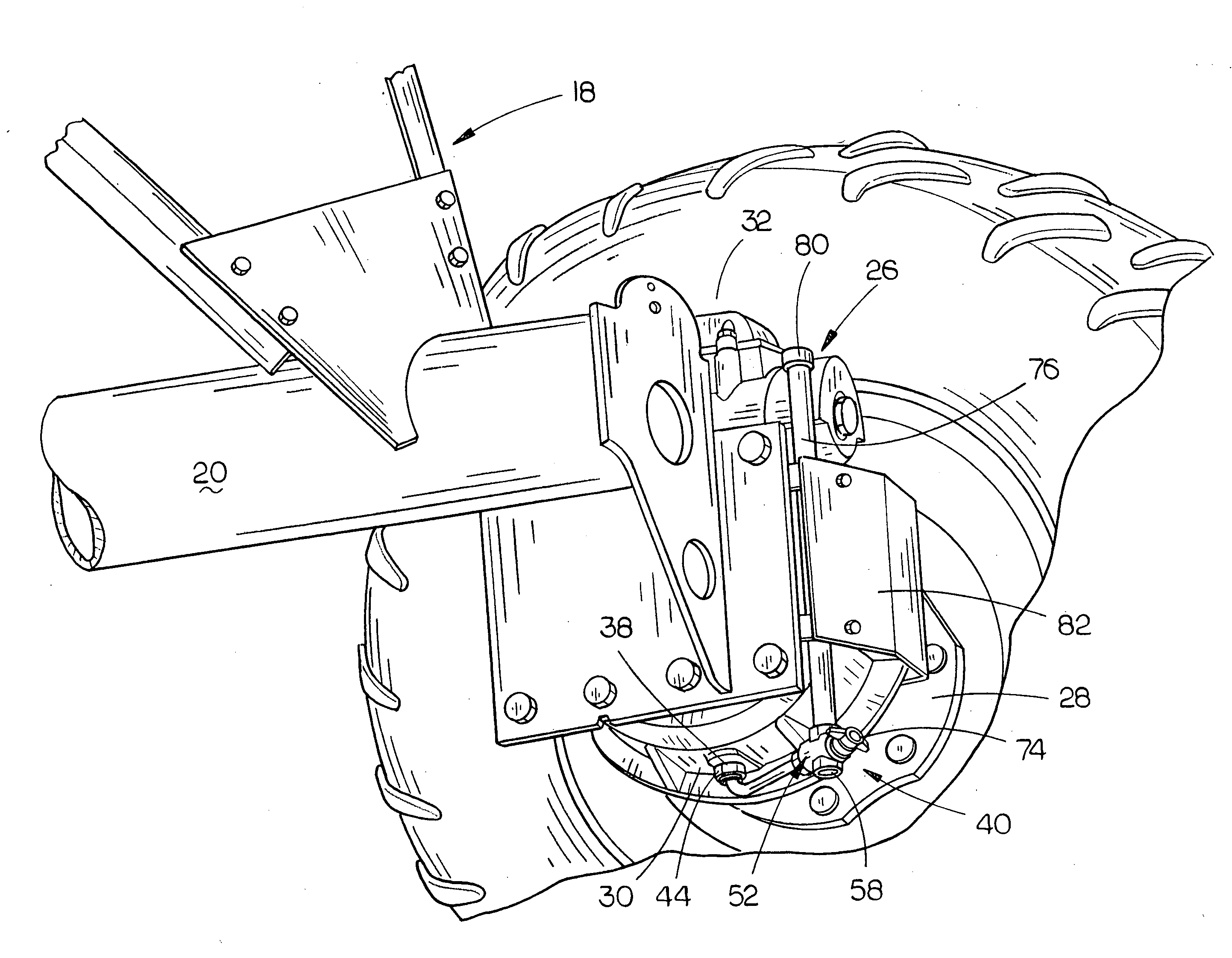
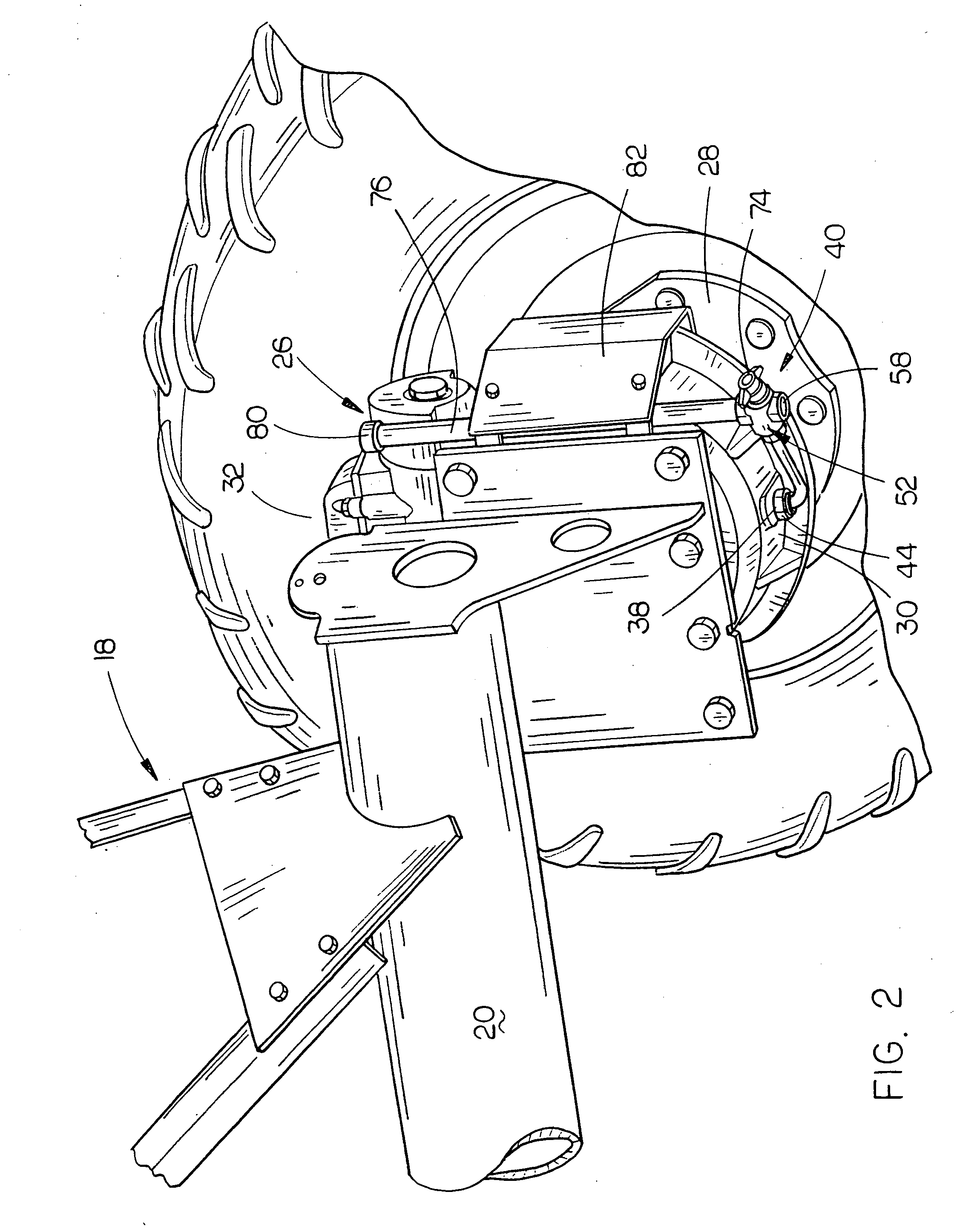
[0008]An upstanding second pipe is secured to the second opening of the valve body and extends upwardly therefrom to a height which is substantially level with the fill opening in the gearbox. When the valve is rotated to a first position, the lower end of the second pipe is in fluid communication with the first pipe so that lubricant may flow through the valve to enable it to be added to the interior of the gearbox. When the valve is rotated to a second position, the first pipe is in communication with the drain opening in the valve so that water or lubricant may be drained from the gearbox. In a position between the first and second positions, the lubricant is prevented from passing through the valve.
[0009]When it is desired to fill the gearbox with lubricant, the oversized cap at the upper end of the second pipe is removed. Lubricant is then funneled or poured into the second pipe and the level of the lubricant in the gearbox will reach the same height and no greater than the height of the lubricant in the second pipe thereby preventing overfilling of the gearbox. When it is desired to drain water or lubricant from the interior of the gearbox, the valve is rotated to its second position so that the lubricant or water from the gearbox may drain outwardly from the drain opening in the valve. When the gearbox is either being filled or drained, the valve is rotated to its second position.
[0010]The assembly of this invention ensures that the gearbox will not be overfilled with lubricant thereby preventing undue pressure being created within the gearbox. The remote location of the upper end of the second pipe from the gearbox makes it convenient to fill the gearbox with lubricant. Further, the remote location of the valve from the gearbox provides a convenient way to either drain water or lubricant from the gearbox or to add lubricant to the gearbox.
[0014]Still another object of the invention is to provide a lubricant fill and drain assembly for a gearbox mounted on a drive unit of a mechanized irrigation system which may be conveniently and easily attached to the gearbox without modification thereof.

Problems solved by technology

Moreover, this Summary is not intended for use as an aid in determining the scope of the claimed subject matter.

Method used


Image

  • Lubricant fill and drain assembly for a gearbox
  • Lubricant fill and drain assembly for a gearbox
  • Lubricant fill and drain assembly for a gearbox

Examples


Embodiment Construction

[0021]Embodiments are described more fully below with reference to the accompanying figures, which form a part hereof and show, by way of illustration, specific exemplary embodiments. These embodiments are disclosed in sufficient detail to enable those skilled in the art to practice the invention. However, embodiments may be implemented in many different forms and should not be construed as being limited to the embodiments set forth herein. The following detailed description is, therefore, not to be taken in a limiting sense in that the scope of the present invention is defined only by the appended claims.

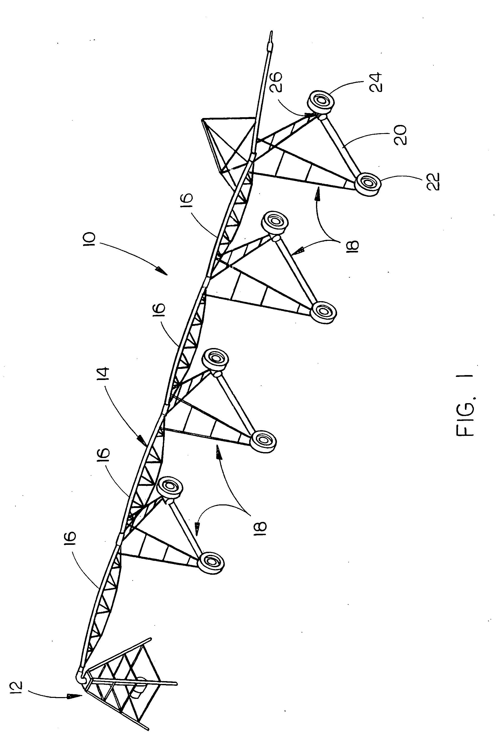
[0022]The numeral 10 refers generally to a mechanized irrigation system such as a center pivot irrigation system. The system 10 conventionally includes a center pivot structure 12 having a main water pipeline 14 extending outwardly therefrom. Pipeline 16 includes a plurality of sprinklers mounted thereon (not shown). The pipeline 14 includes a plurality of span structures which are...


PUM


Abstract

A lubricant fill and drain assembly for a gearbox mounted on a drive unit of a mechanized irrigation system is disclosed which provides a convenient means for adding lubricant to a gearbox and for draining lubricant and / or water from the gearbox from a position somewhat remote from the gearbox. The assembly of this invention not only provides a convenient way of adding lubricant to the gearbox but ensures that the gearbox will not be over filled with lubricant.

Description

BACKGROUND OF THE INVENTION[0001]1. Field of the Invention[0002]This invention relates to a lubricant fill and drain assembly for a gearbox and more particularly to a lubricant fill and drain for a gearbox mounted on a drive unit of a mechanized irrigation system.[0003]2. Description of the Related Art[0004]Mechanized irrigation systems such as center pivot irrigation systems, linear move irrigation systems, and corner systems utilize a plurality of drive units which support a water pipeline and move the same through the field to be irrigated. In most mechanized irrigation systems, a pair of drive wheels are mounted on each of the drive units or drive towers with each of the drive wheels being driven by a gearbox which in turn is driven by an electric motor. Normally, the gearboxes are located closely adjacent the wheels of the drive units which makes it difficult to drain lubricant or water from the gearbox when necessary or to fill the gearbox with lubricant when necessary. If the...

Claims


Application Information

Patent Timeline
IPC IPC(8): F16H57/04
CPCF16H57/0408A01G25/092
Inventor MCGEE, RICKY D.
Owner VALMONT INDUSTIES INC
Learn More