

Illumination device and image display device
a technology of image display and illumination device, which is applied in the direction of fixed installation, lighting and heating apparatus, lighting support device, etc., can solve the problems of long viewing time burden on the eye of the user, brain wave, and damage to the health of the user
- Summary
- Abstract
- Description
- Claims
- Application Information
AI Technical Summary
Benefits of technology
Problems solved by technology
Method used
Image

Examples
first embodiment
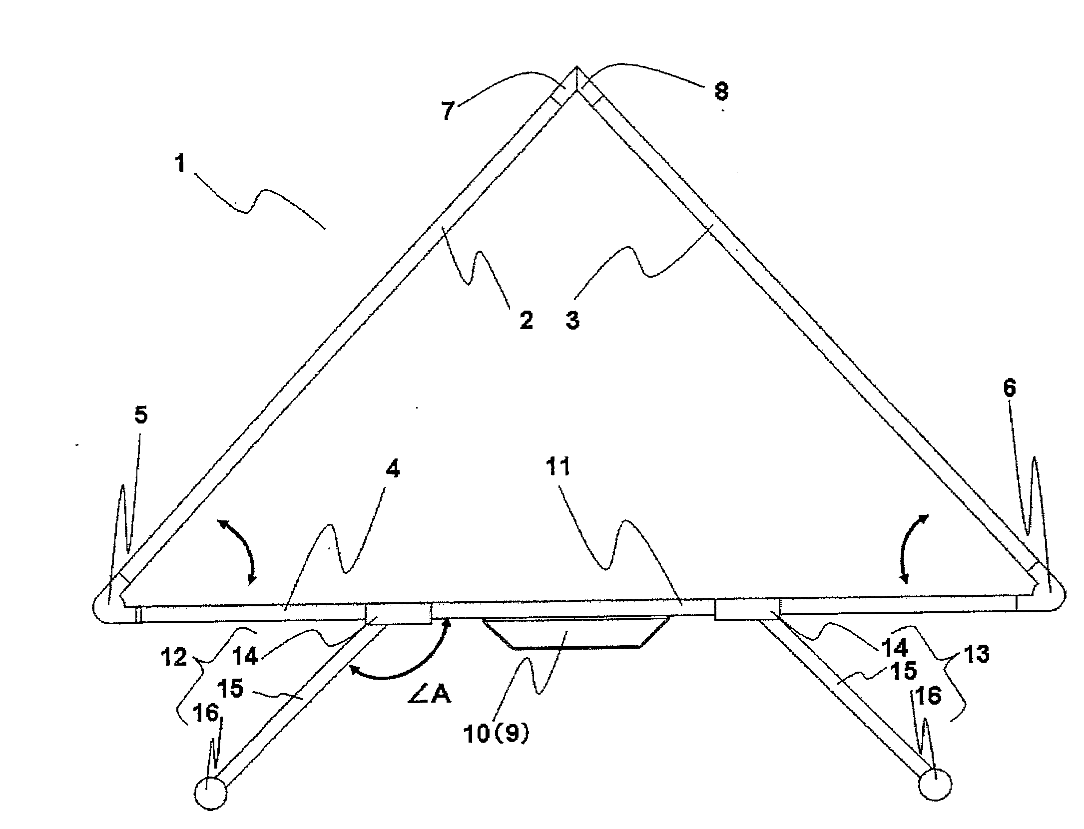
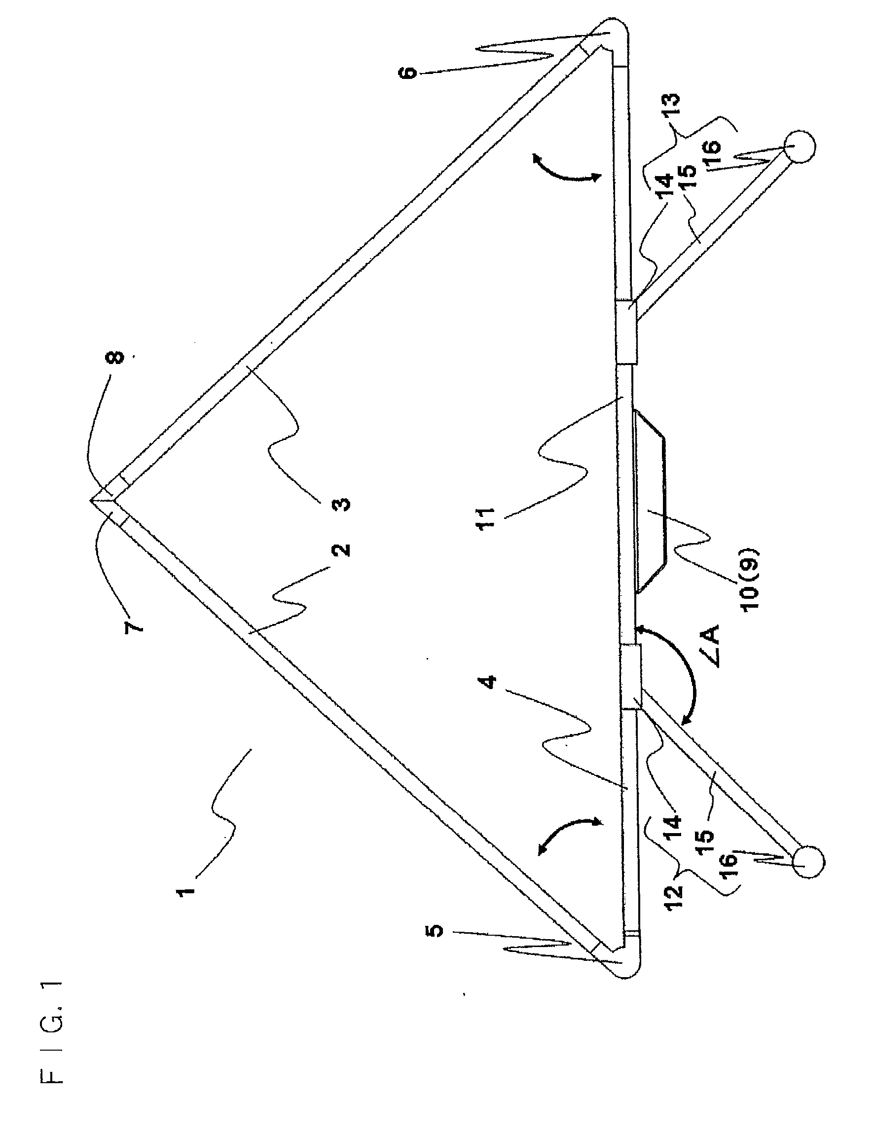
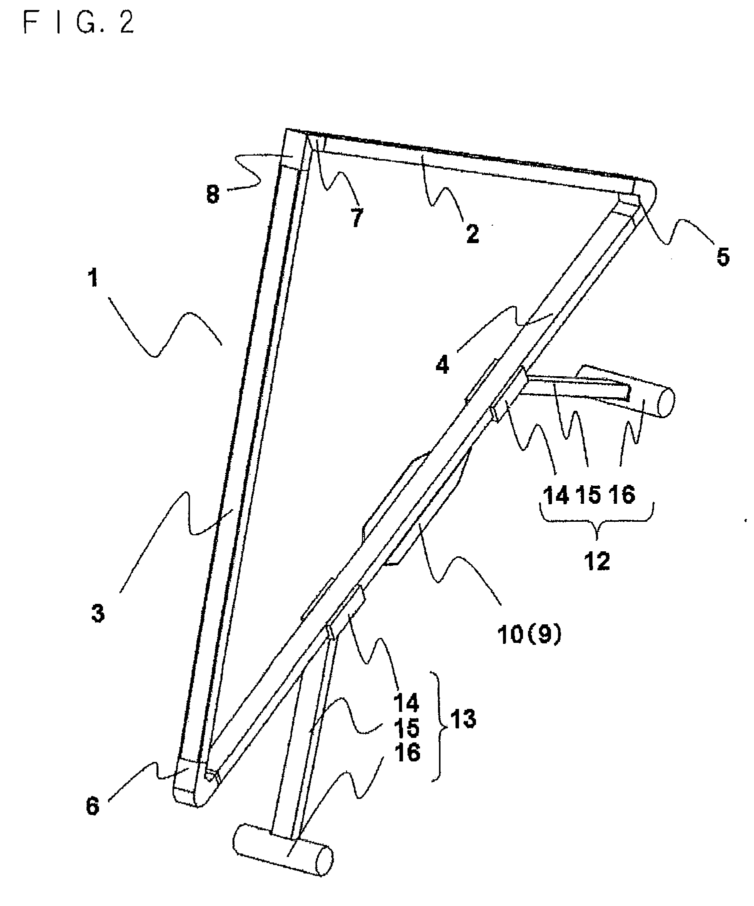
[0089]FIG. 1 is a schematic front view of an illumination device 1 according to a first embodiment of the present invention. FIG. 2 is a schematic perspective view of the illumination device 1 according to the first embodiment of the present invention.
[0090]The illumination device 1 has a first illumination part 2 and a second illumination part 3 having a light emitting diode (described as an LED hereinafter) as a light source; and a support part 4 for supporting the first illumination part 2 and the second illumination part 3, being a plurality of illumination parts. The support part 4 is formed into a quadrangular prism made of aluminum, and the first illumination part 2 and the second illumination part 3 are formed into a shape with a part of the quadrangular prism of aluminum removed for disposing the LED. Structures of the first illumination part 2 and the second illumination part 3 will be described in detail later.
[0091]A first turning part 5 and a second turning part 6 are p...
second embodiment
[0132]Next, an illumination device 41 according to a second embodiment of the present invention will be described with reference to the drawings. Characteristic parts of the second embodiment will be described below, wherein the same reference numerals are assigned to the parts in common with those of the first embodiment, and the description thereof is omitted.
[0133]FIG. 10 is a schematic front view of an illumination body part 42 of the illumination device 41 according to the second embodiment of the present invention. FIG. 11 is a schematic perspective view of the illumination body part 42 of the illumination device 41 according to the second embodiment of the present invention.
[0134]The illumination device 41 according to the second embodiment includes a turning mechanism capable of turning in multiple directions (two directions), unlike the first embodiment wherein a first illumination part 43 and a second illumination part 44 can be turned only one direction with respect to th...
third embodiment
[0141]Next, an illumination device 61 according to a third embodiment of the present invention will be described with reference to the drawings. Characteristic parts of the third embodiment will be described below, wherein the same reference numerals are assigned to the parts in common with those of the first or second embodiment, and the description thereof is omitted.
[0142]FIG. 13 is a schematic front view of an illumination body part 62 of the illumination device 61 according to the third embodiment of the present invention. FIG. 14 is a schematic perspective view of the illumination body part 62 of the illumination device 61 according to the third embodiment of the present invention. FIG. 15 is a schematic enlarged view of the turning mechanism of the illumination device 61 according to the third embodiment of the present invention.
[0143]As with the second embodiment, the illumination device 61 according to the third embodiment has the turning mechanism capable of turning in mul...
PUM
 Abstract
Description
Claims
Application Information