Floor Panel and Floating Floor System Incorporating the Same

Inactive Publication Date: 2010-09-30
AFI LICENSING
View PDF12 Cites 18 Cited by
  • Summary
  • Abstract
  • Description
  • Claims
  • Application Information

AI Technical Summary

Problems solved by technology

For example, the gaps may cause buckling at a top surface of the top layer.
Alternatively, when the floor panels are assembled such that the ends of the bottom layers of the adjacent floor panels substantially abut, unwanted gaps or overlapping can occur between the ends of the bottom layers due to deviations in the size of the marginal end portions and/or errors occurring during installation.
Additionally, the marginal end portions of the top layer of a first row of the floor panels, which are typically positioned adjacent a wall, remain unsupported when the floating floor system is assembled, because the marginal end portions of the top layer of the first row of the floor panels will not engage with an adjacent floor panel.
Thus, because the thickness of the bottom layer is significantly large, the gap occurring between the

Method used


Image

  • Floor Panel and Floating Floor System Incorporating the Same
  • Floor Panel and Floating Floor System Incorporating the Same
  • Floor Panel and Floating Floor System Incorporating the Same

Examples


Embodiment Construction

)

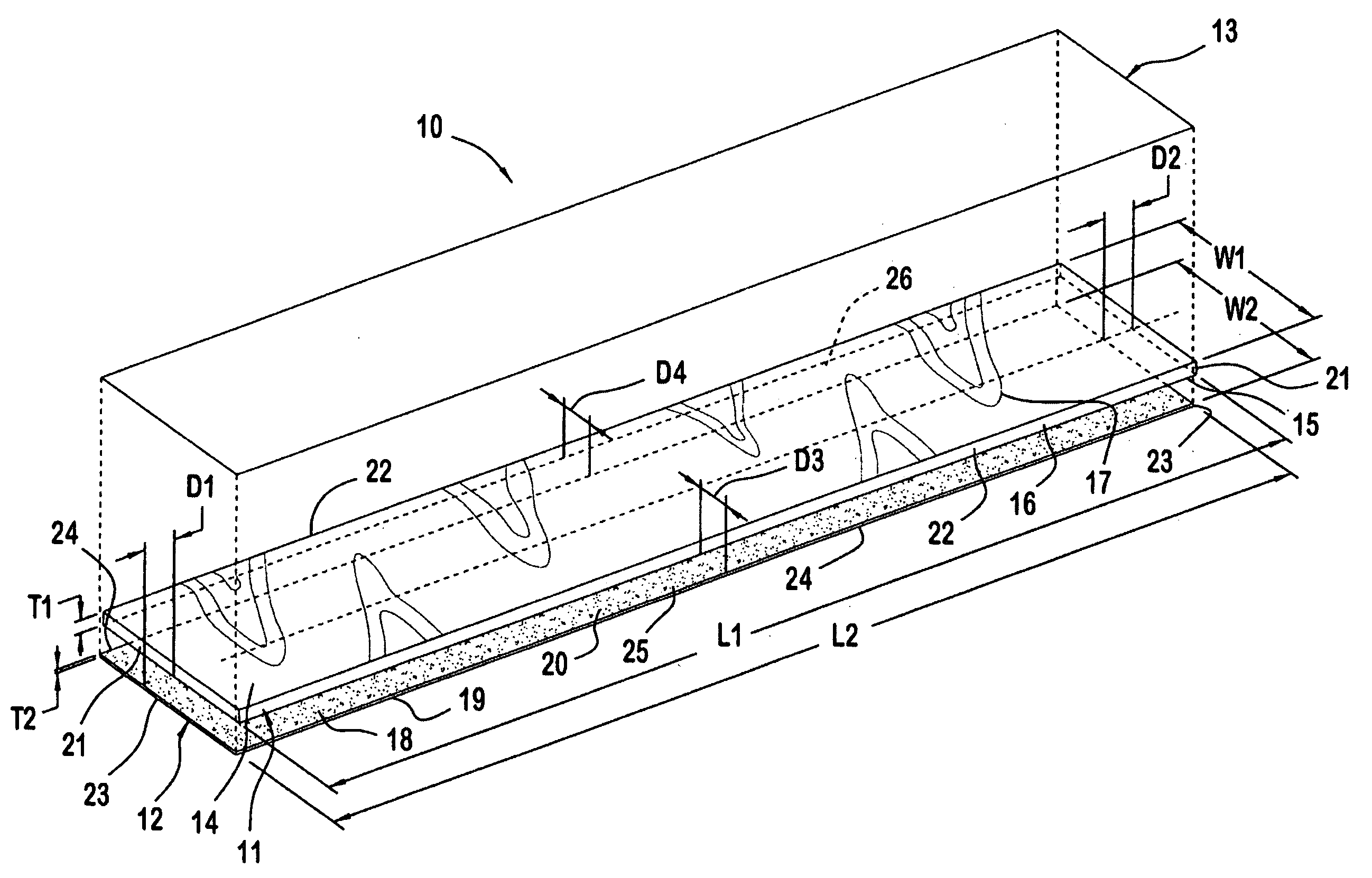
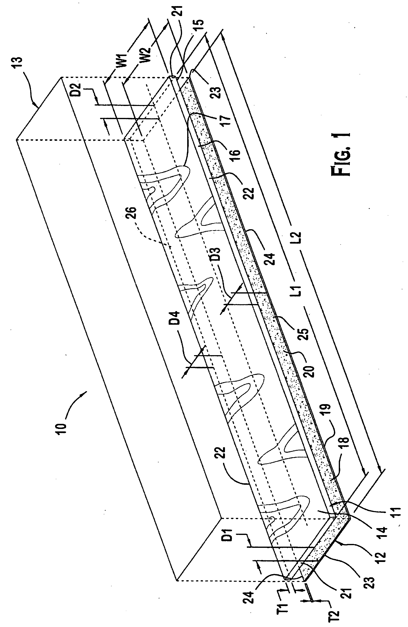
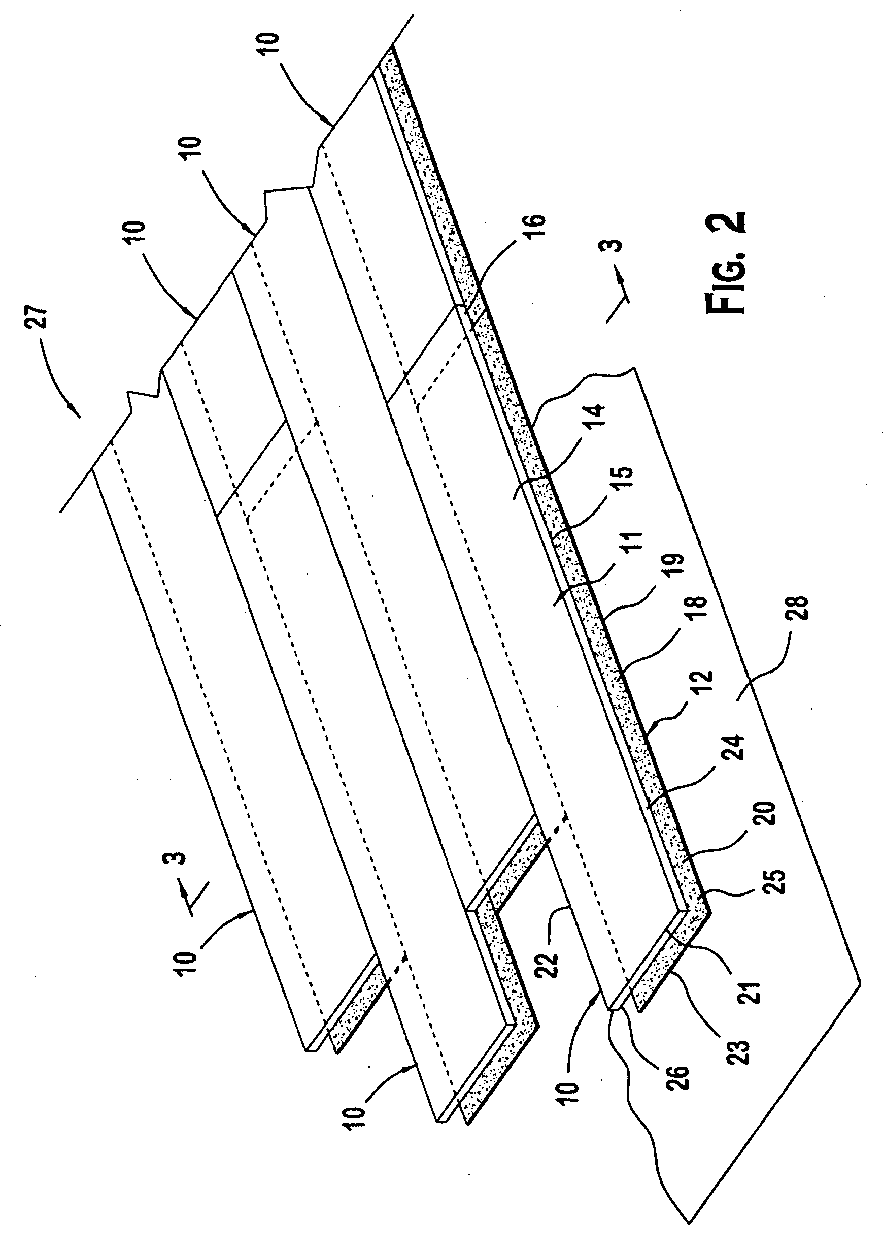
[0018]FIGS. 1-3 show a floor panel 10 according to a first embodiment of the invention. As shown in FIG. 1, the floor panel 10 comprises a top layer 11, a bottom layer 12, and a release member 13. The top layer 11 may be formed, for example, from a substantially flexible sheet material, such as plastic, vinyl, polyvinyl chloride, polyester, or combinations thereof. The top layer 11 has a top surface 14 with a visible decorative pattern 17 and a bottom surface 15. In the illustrated embodiment, the top layer 11 comprises at least one mix layer 16, a print film provided with the visible decorative pattern 17, a wear layer (not shown), and a top coat (not shown), respectively. It will be appreciated by those skilled in the art that although the top layer 11 is shown and described herein as comprising multiple layers that the top layer 11 may alternatively comprise a single layer. Additionally, the types of layers constituting the top layer 11 and the visible decorative pattern 17 coul...


PUM

PropertyMeasurementUnit
Thicknessaaaaaaaaaa
Thicknessaaaaaaaaaa
Thicknessaaaaaaaaaa

Abstract

A floor panel and a floating floor system incorporating the floor panel include a floor panel having a top layer and a bottom layer. The top layer has a top surface and a bottom surface. The top surface has a visible decorative pattern. The bottom layer has a top surface and a bottom surface. The top surface of the bottom layer is adhered to the bottom surface of the top layer such that the bottom layer is offset from the top layer in a direction of length and width and a marginal end portion of the top surface of the bottom layer and a marginal end portion of the bottom surface of the top layer is exposed. At least one of the marginal end portions has an adhesive, and a ratio of a thickness of the top layer to a thickness of the bottom layer is about 5 or greater.

Description

FIELD OF THE INVENTION[0001]The present invention relates to a floor panel comprising a top layer and a bottom layer adhered together in an offset relationship such that a marginal end portion of a top surface of the bottom layer and a marginal end portion of a bottom surface of the top layer are exposed wherein at least one of the marginal end portions has an adhesive, and a ratio of a thickness of the top layer to a thickness of the bottom layer is about 5 or greater. The present invention further relates to a floating floor system incorporating the same.BACKGROUND OF THE INVENTION[0002]Floor panels for use in floating floor systems typically comprise a top layer and a bottom layer adhered together in an offset relationship such that a substantially L-shaped marginal end portion of a top surface of the bottom layer and a substantially L-shaped marginal end portion of a bottom surface of the top layer are exposed. The top layer typically comprises at least one mix layer, a print fi...

Claims


Application Information

Patent Timeline
IPC IPC(8): B32B33/00
CPCE04F15/107E04F2203/065E04F15/105Y10T428/1476E04F2201/07E04F2290/043Y10T428/24802E04F2201/0138
Inventor BALMER, RICHARD H.ESHBACH, JR., JOHN R.ANSPACH, KEAN M.HARRINGTON, HEATHBUCKWALTER, MICHAEL E.STOLL, BRENT L.
Owner AFI LICENSING
Why Eureka
Try Eureka