

Pneumatic tire
Active Publication Date: 2010-10-07
SUMITOMO RUBBER IND LTD
View PDF25 Cites 41 Cited by
- Summary
- Abstract
- Description
- Claims
- Application Information
AI Technical Summary
Benefits of technology
[0006]It is therefore, an object of the present invention to provide a pneumatic tire having a unidirectional tread pattern which can improve the stee
Problems solved by technology
However, if the land ratio becomes increased, since the volume of tread grooves is decreased, a shearing force of snow trodden and packed in the tread grooves decreases, and on-the-snow performance tends to deteriorate.
If a large number of sipes
Method used
View moreImage
Smart ImageViewing Examples

Examples
 PUM
 Abstract
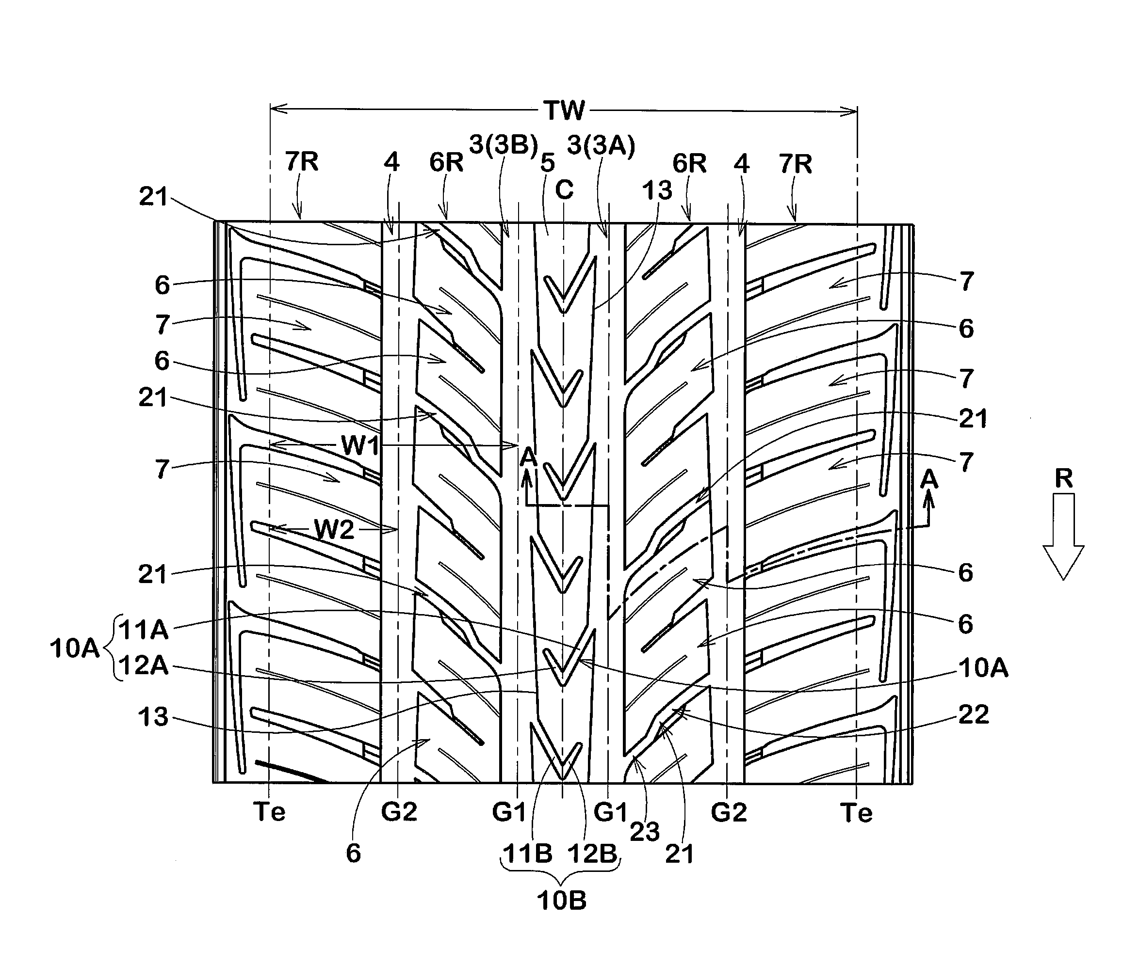
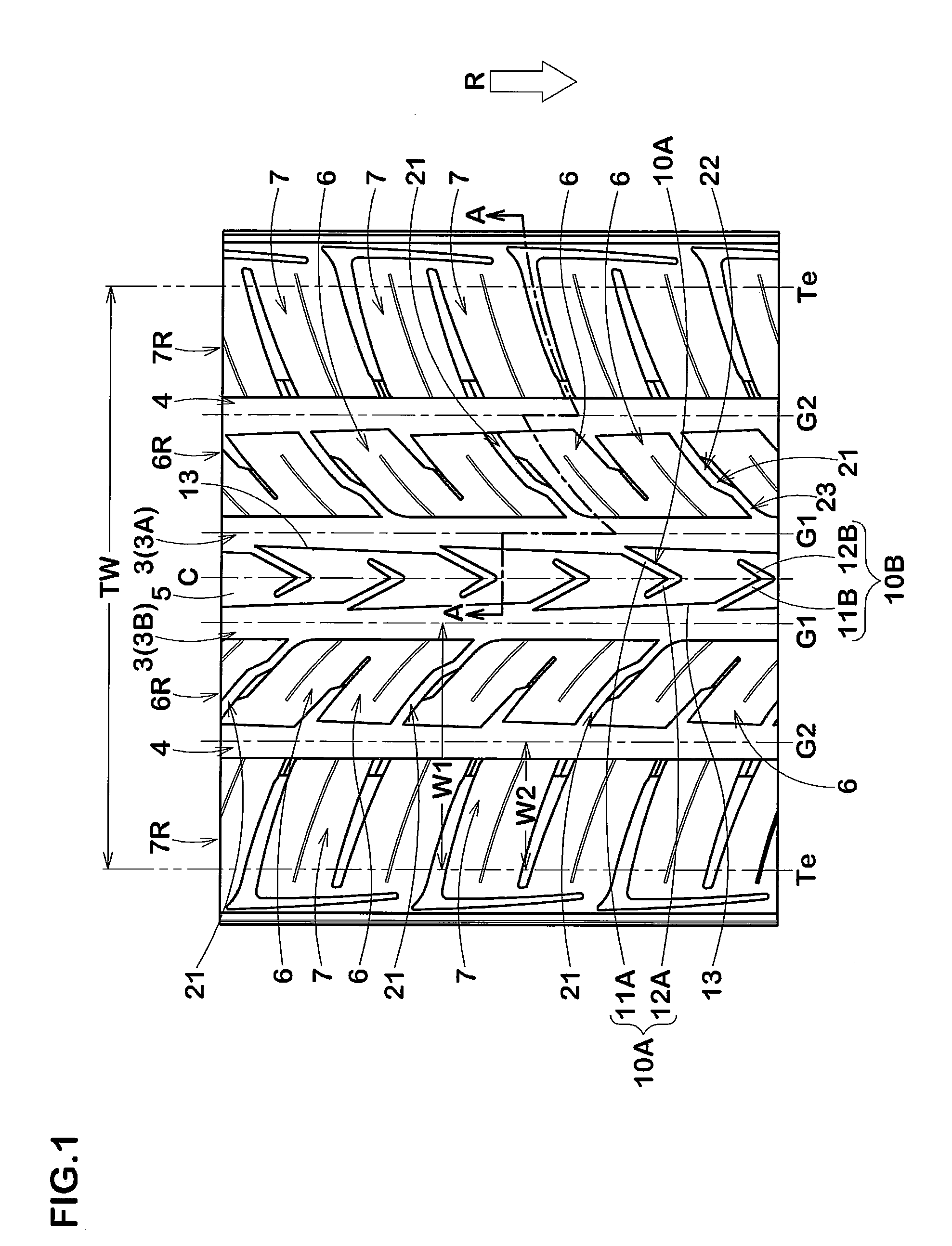
A pneumatic tire has a unidirectional tread pattern comprising right-hand and left-hand crown circumferential grooves and a crown rib formed therebetween. The crown rib is provided with first and second V-shaped grooves arranged alternately in the tire circumferential direction. The first V-shaped grooves extend from the left-hand crown circumferential groove. The second V-shaped grooves extend from the right-hand crown circumferential groove. The first and second V-shaped grooves are terminated within the rib, and their V-shape configurations have bending points substantially positioned at the tire equator.
Description
BACKGROUND OF THE INVENTION[0001]The present invention relates to a pneumatic tire, more particularly to a unidirectional tread pattern suitable for running on dry pavements as well as snowy / icy pavements.[0002]Heretofore, in order to improve steering stability on dry pavements, a widely employed technique is to increase the land ratio of the tread pattern as far as possible, in other words, to increase the tread pattern rigidity, namely, overall rigidity of tread elements such as block, rib and the like. However, if the land ratio becomes increased, since the volume of tread grooves is decreased, a shearing force of snow trodden and packed in the tread grooves decreases, and on-the-snow performance tends to deteriorate.[0003]When the shearing force of the packed snow is large, it can produce a large traction force or braking force, therefore, good snow grip performance can be obtained.[0004]On the other hand, in order improve steering stability on snowy / icy pavements, a widely empl...
Claims
Login to View More Application Information
Patent Timeline
 IPC IPC(8): B60C11/13
CPCB60C11/0302B60C11/0309B60C11/13B60C11/1369B60C2011/0395B60C2011/0362B60C2011/0388B60C2011/0369B60C2011/0381B60C2011/036
InventorMUKAI, TOMOYUKI
OwnerSUMITOMO RUBBER IND LTD