Resilient plug, fluid proof construction and connector

Active Publication Date: 2010-10-07
SUMITOMO WIRING SYST LTD
View PDF14 Cites 10 Cited by
  • Summary
  • Abstract
  • Description
  • Claims
  • Application Information

AI Technical Summary

Benefits of technology

[0010]The invention relates to a resilient plug, particularly a rubber plug, to be mounted on a wire connected to a rear end portion of a terminal fitting. The terminal fitting and the plug are inserted into a cavity of a connector housing. The plug has at least one outer lip to be held in close contact with the inner circumferential surface of the cavity while being resiliently deformed. The plug also has at least one inner lip to be held in close contact with the outer circumferential surface of the wire while being resiliently deformed. An outer virtual deforming portion is defined as an area of the outer lip that is not resiliently deformed and that is radially outward of a virtual line corresponding to the inner

Problems solved by technology

Therefore sealing between the outer lips and the inner circumferential surface of the cavity may become unstable.
As a result, a waterproof property between the wire

Method used


Image

  • Resilient plug, fluid proof construction and connector
  • Resilient plug, fluid proof construction and connector
  • Resilient plug, fluid proof construction and connector

Examples


Embodiment Construction

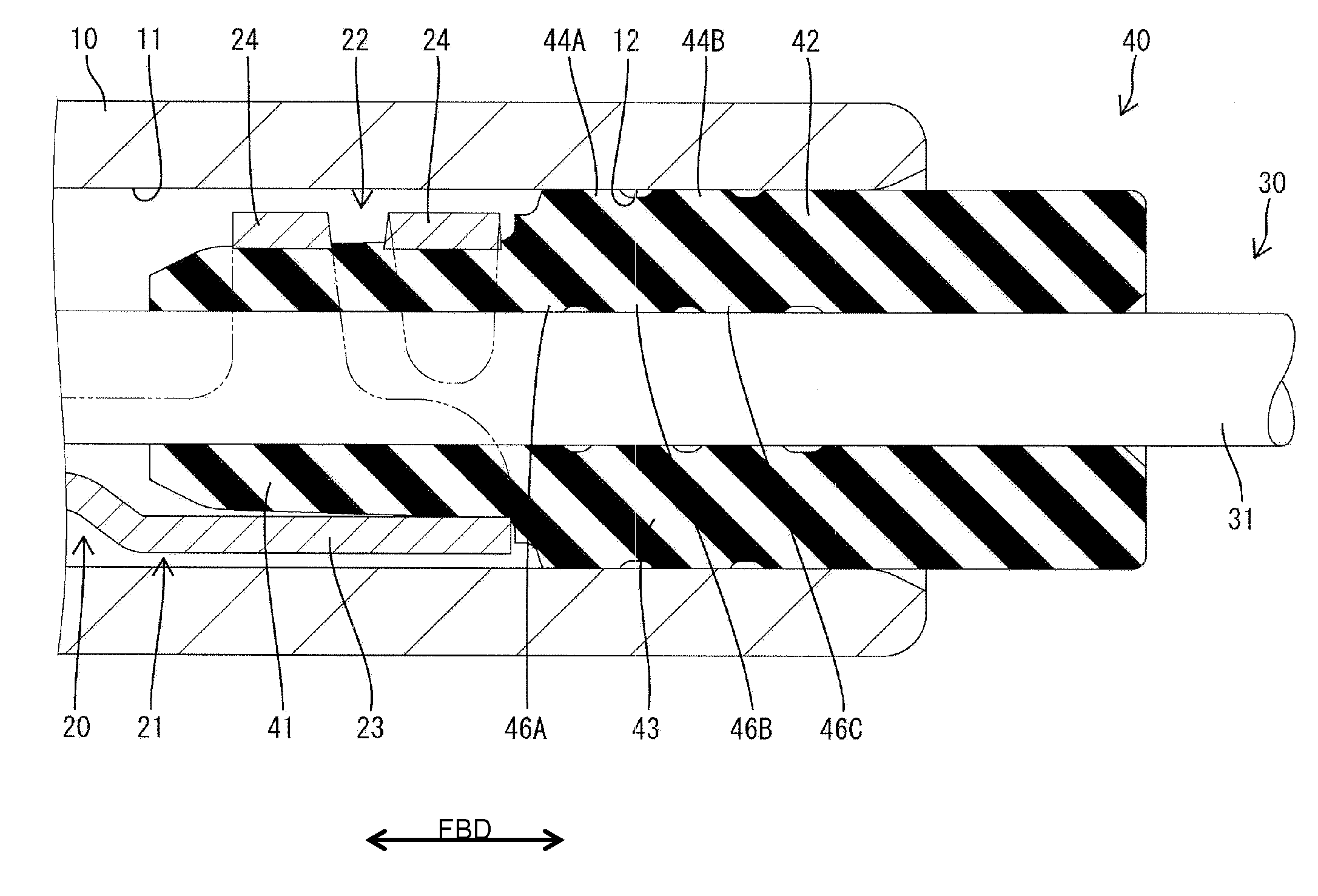
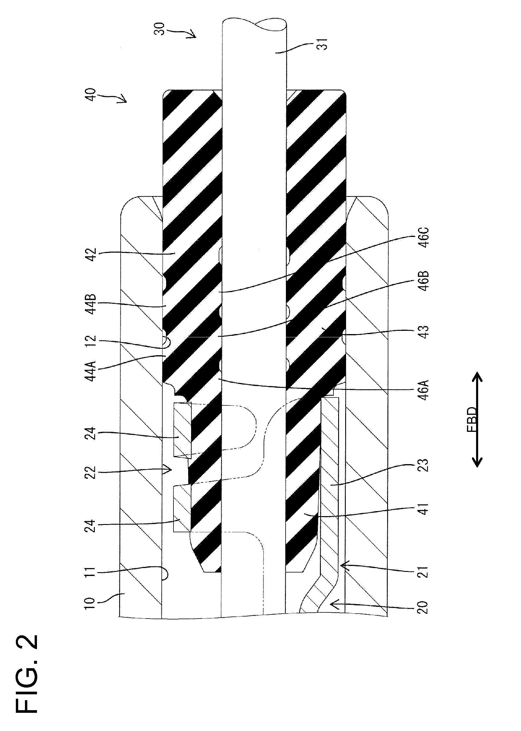
[0039]A first embodiment of the invention is described with reference to FIGS. 1 to 4. A connector 1 of this embodiment is provided with a housing 10 made e.g. of synthetic resin, a conductive metallic terminal fitting 20, a wire 30 and a resilient plug 40, preferably a rubber plug 40. The connector housing 10 is formed with a cavity 11 which makes an opening in a rear opening surface of the connector housing 10, and a rear end portion of the inner circumferential surface of the cavity 11 serves as a sealing surface 12 having an axis line extending in forward and backward directions FBD and a circular cross section.

[0040]The terminal fitting 20 is narrow and long in forward and backward directions FBD and a crimping portion 21 to connect the wire 30 is formed at or near a rear end portion. Particularly, the crimping portion 21 is of a known form, wherein one or more, preferably a pair of crimping pieces 24 stand up or project from the lateral (preferably substantially opposite left ...


PUM


Abstract

A rubber plug (40) is provided with a stable sealing property while reducing frictional resistance when the rubber plug (40) is inserted into a cavity. In a cross section including axis lines of the rubber plug (40), a cavity (11) and a wire (30), areas of outer lips (44A, 44B) not resiliently deformed radially outward of a virtual line (12L) corresponding to the inner circumferential surface of the cavity (11) are specified as outer virtual deforming portions (45A, 45B), areas of inner lips (46A, 46B and 46C) not resiliently deformed radially inward of a virtual line (31L) corresponding to the outer circumferential surface of the wire (30) are specified as inner virtual deforming portions (47A, 47B, and 47C) and at least parts of the inner virtual deforming portions (47A, 47B and 47C) correspond to only parts of the outer virtual deforming portions (45A, 45B).

Description

BACKGROUND OF THE INVENTION[0001]1. Field of the Invention[0002]The invention relates to a resilient plug, particularly a rubber plug, to a fluidproof construction and to a connector.[0003]2. Description of the Related Art[0004]U.S. Pat. No. 6,764,329 discloses a rubber plug to be mounted on a wire connected with a terminal fitting and inserted into a cavity of a connector housing. Outer lips are formed on the outer circumferential surface of the rubber plug and closely contact the inner circumferential surface of the cavity while being resiliently deformed. Inner lips are formed on the inner circumferential surface of the rubber plug and closely contact the outer circumferential surface of the wire while being resiliently deformed.[0005]The rubber plug is formed so that the inner and outer lips are displaced in a longitudinal direction to reduce frictional resistance when the rubber plug is inserted. Thus, no inner lips are present in areas of the inner circumferential surface alig...

Claims


Application Information

Patent Timeline
IPC IPC(8): H01R13/52H02G15/013F16J15/06
CPCH01R13/521H01R13/5205
Inventor YOSHIOKA, CHIKAHIRONAKAYAMA, YASUAKI
Owner SUMITOMO WIRING SYST LTD
Why Eureka
Try Eureka