Locking element and bolted joint

Inactive Publication Date: 2010-10-14
NORD LOCK AB (SE)
View PDF12 Cites 13 Cited by
  • Summary
  • Abstract
  • Description
  • Claims
  • Application Information

AI Technical Summary

Problems solved by technology

The washers are used in pairs, the cam pattern surfaces facing each other, and the cam pitch exceeding the pitch of the bolt element threads, which causes a locking effect against untightening o

Method used


Image

  • Locking element and bolted joint
  • Locking element and bolted joint
  • Locking element and bolted joint

Examples


Embodiment Construction

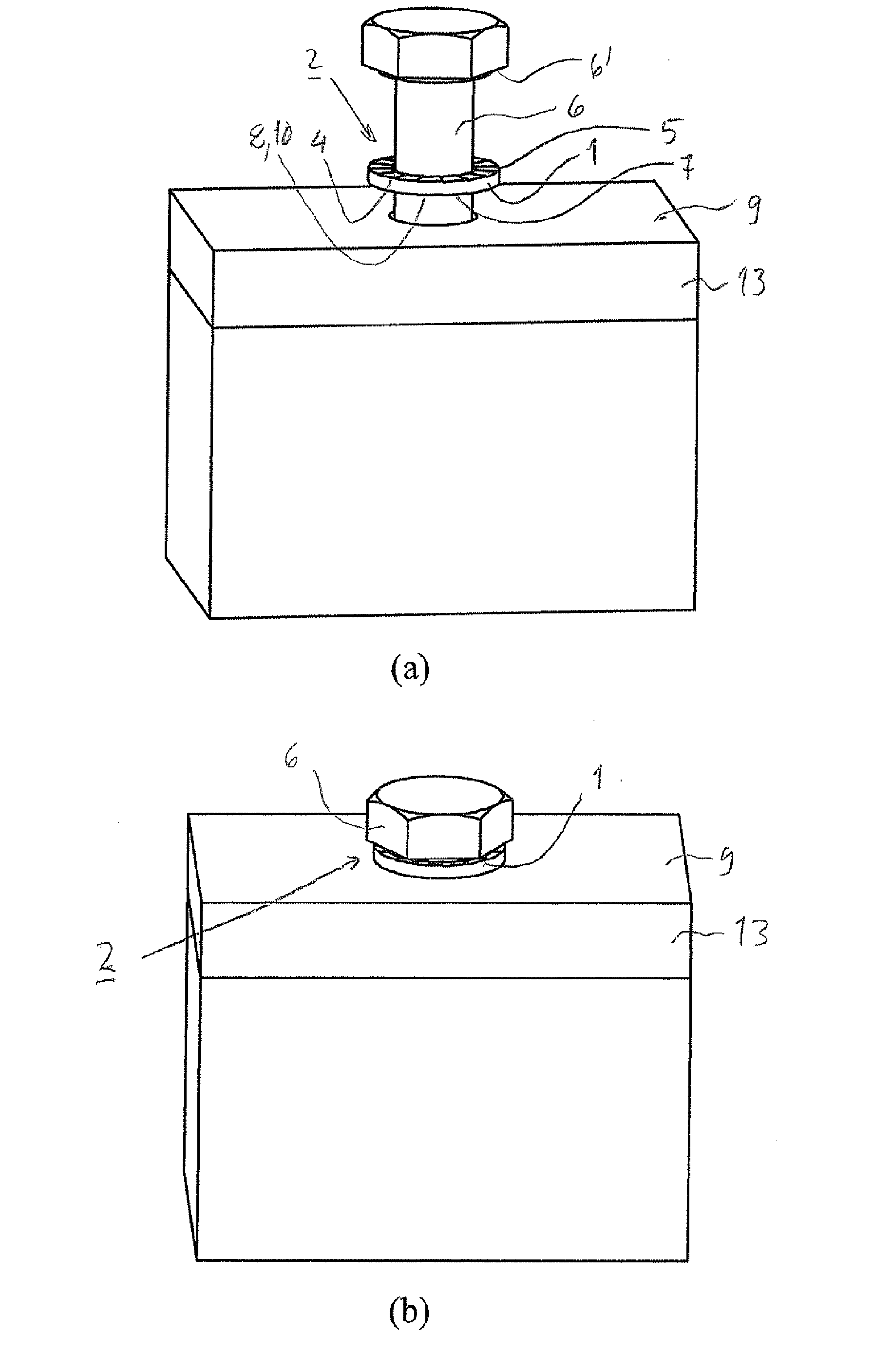
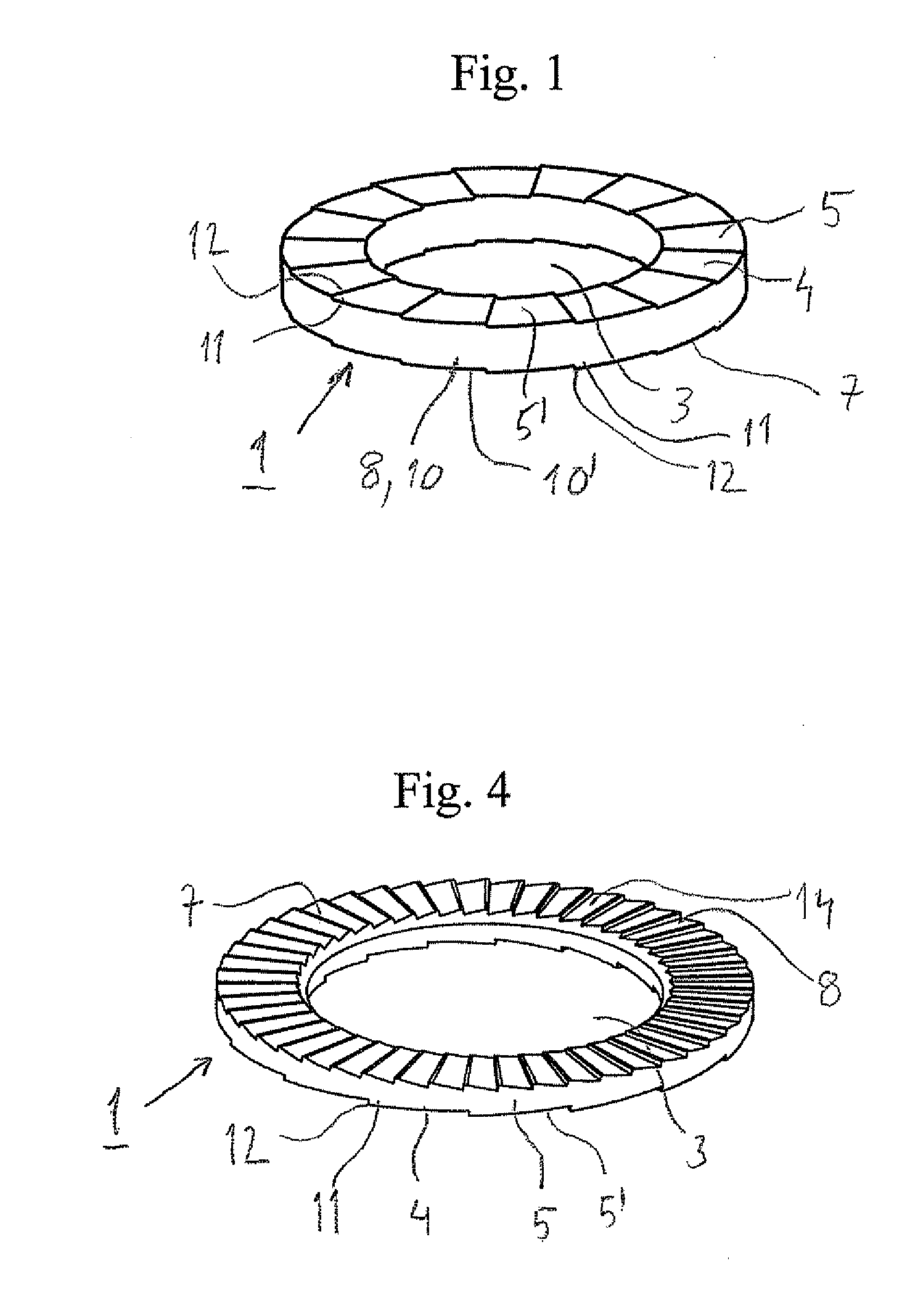
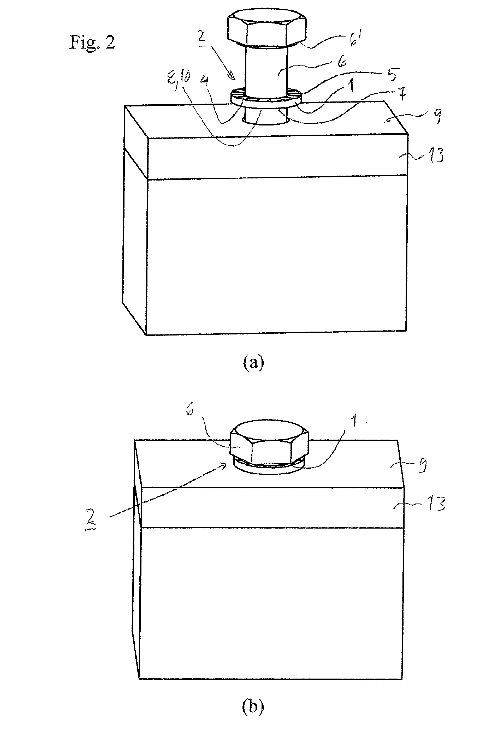
[0018]In FIG. 1, 1 designates a first embodiment of a locking washer according to the present invention the washer being intended for locking in a bolted joint 2, FIG. 2.

[0019]The washer comprises a central hole 3 and one side 4 comprising a pattern of radially extending cams 5, the main surface 5′ of which having a helix configuration, the pitch of the main surface exceeding the pitch of the threads of the bolt element 6, bolt or nut, that the washer is intended to lock.

[0020]Contrary to the normal use in pairs of locking washers of this kind, the washer according to the invention is intended to be applied as a single locking element in the joint as can be seen in eg FIG. 2(a).

[0021]The other, the opposite, side 7 of the washer comprises mechanical means 8 for preventing rotation between said other side and a surface 9, against which said other side is intended to act in the joint as tightened.

[0022]According to a preferred embodiment said mechanical means of said other side 7 comp...


PUM


Abstract

A locking element for locking in a bolted joint, the locking element comprising one side comprising a pattern of radially extending cams, the main surface of which having a helix configuration, the pitch of the cams exceeding the pitch of the threads involved in the bolted joint. The locking element is especially characterized in that the locking element is a washer intended to be applied as a single locking element in the joint and in that the other, the opposite, side of the washer comprises mechanical means for providing a locking action for preventing rotation between said other side and a surface against which said other side is intended to act. The invention also relates to a bolted joint.

Description

BACKGROUND[0001]1. Technical Field[0002]The present invention relates to a locking element according to the introductory part of the attached claim 1.[0003]The invention also relates to a bolted joint according to the attached claim 9.[0004]2. Prior Art[0005]Washers for locking purposes in bolted joints are previously known and normally comprises a central hole for a bolt element, one side with a pattern of radially extending teeth and the other side with a pattern of radially extending cams. The washers are used in pairs, the cam pattern surfaces facing each other, and the cam pitch exceeding the pitch of the bolt element threads, which causes a locking effect against untightening of the bolted joint.[0006]The fact that a pair of washers are necessary for locking causes comparatively complicated mounting of the joint. Further, forming of the different patterns necessitates different dies etc. Furthermore, the washer cost of a bolted joint is considerable.[0007]The object of the pre...

Claims


Application Information

Patent Timeline
IPC IPC(8): F16B43/00
CPCF16B39/24F16B43/00F16B39/282F16B39/108
Inventor ANDERSSON, MATTIAS
Owner NORD LOCK AB (SE)
Why Eureka
Try Eureka